to ground.
When used with an amplifier with balanced inputs, the wiring of the output XLR is simply pin to pin (1 to 1,
etc.), the polarity of the signal being preserved if the source connected to the input is also balanced (see
previous section).
Where an amplifier with unbalanced inputs is used, the connections should be made as follows :
• Where the source connected to the PS TDcontroller input is pin 3 hot, connect the hot pin of the amplifier
to pin 3 of the PS TDcontroller XLR output connector and the amplifier ground to pin 2.
• Where the source is wired pin 2 hot, connect the hot pin of the amplifier input to pin 2 of the XLR output
connector, and the amplifier ground to pin 3.
• Leave pin 1 of the output XLR unconnected.
This wiring method avoids any loss of output level, provided that the ground of the PS TDcontroller stays
floating relative to that of the amplifier -thus care should be taken with regard to the Earth Lift switch when
it is depressed: the respective signal grounds could possibly be linked together via the mains earth).
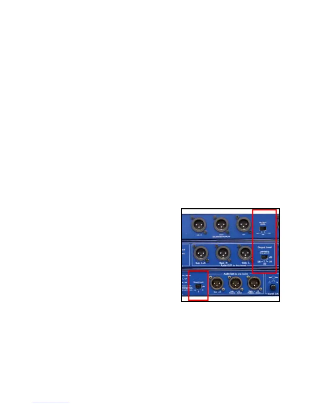
Output Level Switch
The 3 position output level switch has two main purposes :
1. Once the sense lines are connected, this switch is only used to match the processor gain to the amplifier
gain for optimum signal to noise ratio. Having selected the appropriate output level, the signal to noise
ratio will be preserved whatever the gain of the amplifier (for a broader explanation of this please refer to
page 28).
2. If the sense lines are disconnected, the TDcontroller is
operating in fall back mode (Does not apply to PS15
MKII). In this case, selecting the proper switch
setting is absolutely essential to ensure the correct
operation of the protection circuits. For the PS8TD
(labels –12dB –6dB OdB) an attenuation of 12dB
should be made for 38dB amplifier gain and 6dB for
32dB amplifier gain. (the 0dB position corresponds to
26dB amplifier gain)
The three gain values available are 26, 32 or 38 dB
and correspond to the positions left, middle and right of
the switch respectively. If the effective gain of the
amplifiers doesn’t correspond to any of the three
positions the closest should be selected. In case of
doubt, the lesser value should be chosen.
For the PS15TD The three gain values available are +6dB, 0 & -6dB. For minimum noise floor the -6dB
setting should be chosen, for maximum headroom the +6dB position should be used.