© National Instruments Corporation 65 NI cDAQ-9178/9174 User Guide and Specifications
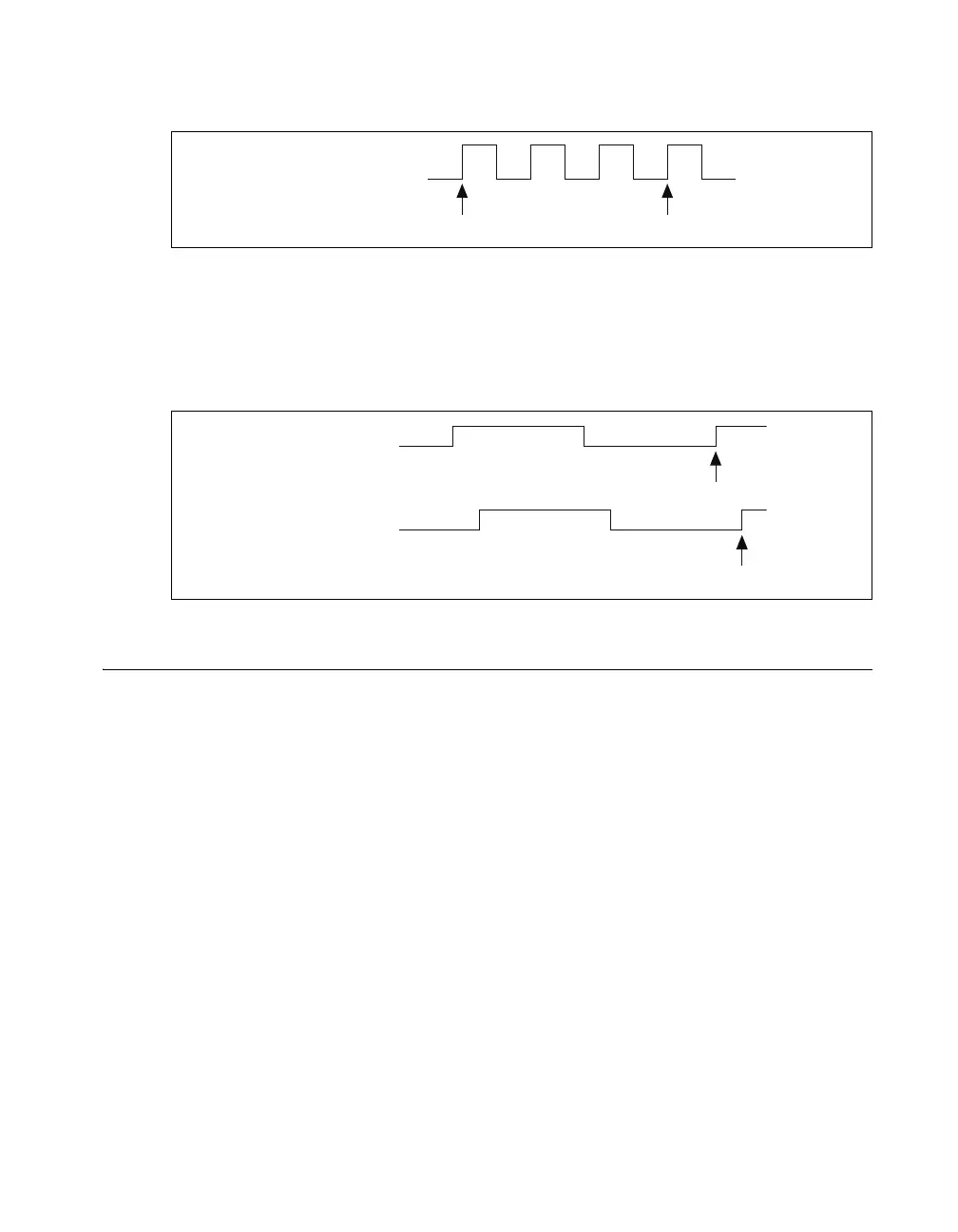
80 MHz Source Mode
In 80 MHz source mode, the device synchronizes signals on the rising edge of the source, and counts on
the third rising edge of the source. Edges are pipelined so no counts are lost, as shown in Figure 57.
Figure 57. 80 MHz Source Mode
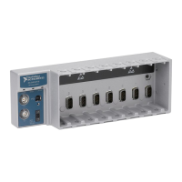
External or Internal Source Less than 20 MHz
With an external or internal source less than 20 MHz, the device generates a delayed Source signal by
delaying the Source signal by several nanoseconds. The device synchronizes signals on the rising edge
of the delayed Source signal, and counts on the following rising edge of the source, as shown in
Figure 58.
Figure 58. External or Internal Source Less than 20 MHz
Digital Routing and Clock Generation
The digital routing circuitry has the following functions:
• Manages the flow of data between the bus interface and the acquisition/generation sub-systems
(analog input, analog output, digital I/O, and the counters). The digital routing circuitry uses FIFOs
(if present) in each sub-system to ensure efficient data movement.
• Routes timing and control signals. The acquisition/generation sub-systems use these signals to
manage acquisitions and generations. These signals can come from the following sources:
– Your C Series I/O modules
– User input through the PFI terminals using hardware-timed digital C Series I/O modules or
the NI cDAQ-9178 chassis PFI terminals.
• Routes and generates the main clock signals for the NI cDAQ-9178/9174 chassis. To determine the
signal routing options for C Series I/O modules installed in the NI cDAQ-9178/9174 chassis, refer
to the Device Routes tab in MAX.
80 MHz Source
Synchronize Count
Source
Delayed Source
Synchronize
Count