Step controlled
additional heat
GENERAL
This function enables an external additional heater, e.g.
an electric boiler, to aid with heating.
With AXC 30, three potential-free relays can be used for
additional heat control, which then gives max. 3 linear
or 7 binary steps. Inside the control module, a further
three potential-free relays can be used for additional
heat control, which then provides a further 3 linear or 7
binary steps.
The flow through the additional heat is ensured by the
external circulation pump (EB1-GP10).
PIPE CONNECTIONS
The external circulation pump (EM1-GP10) is placed on
the supply line to the climate system after the temper-
ature sensor (AA35-BT25).
If the climate system’s flow exceeds the maximum re-
commended flow for the electric boiler, a bypass must
be installed so that only a partial flow passes through
the electric boiler.
TEMPERATURE SENSOR
• The external supply temperature sensor (AA35-BT25),
connected in the indoor module’s control module,
must be installed on the supply line to the climate
system after the additional heat.
Install the temperature sensors using cable ties, together
with the heat conducting paste and aluminium tape.
Then insulate with the enclosed insulation tape.
NOTE
To prevent interference, sensor cables to ex-
ternal connections must not be laid close to
high voltage cables.
SYSTEM DIAGRAM
Caution
This is an outline diagram. Actual installations
must be planned according to applicable
standards.
EXPLANATION
Step controlled additional heatEB1
AXC moduleAA25
External heating medium pumpGP10
SMO S40AA35
External supply temperature sensorBT25
External return line sensorBT71
Miscellaneous
Shut-off valveQM42-43
Trim valveRN1
Non-return valveRM1
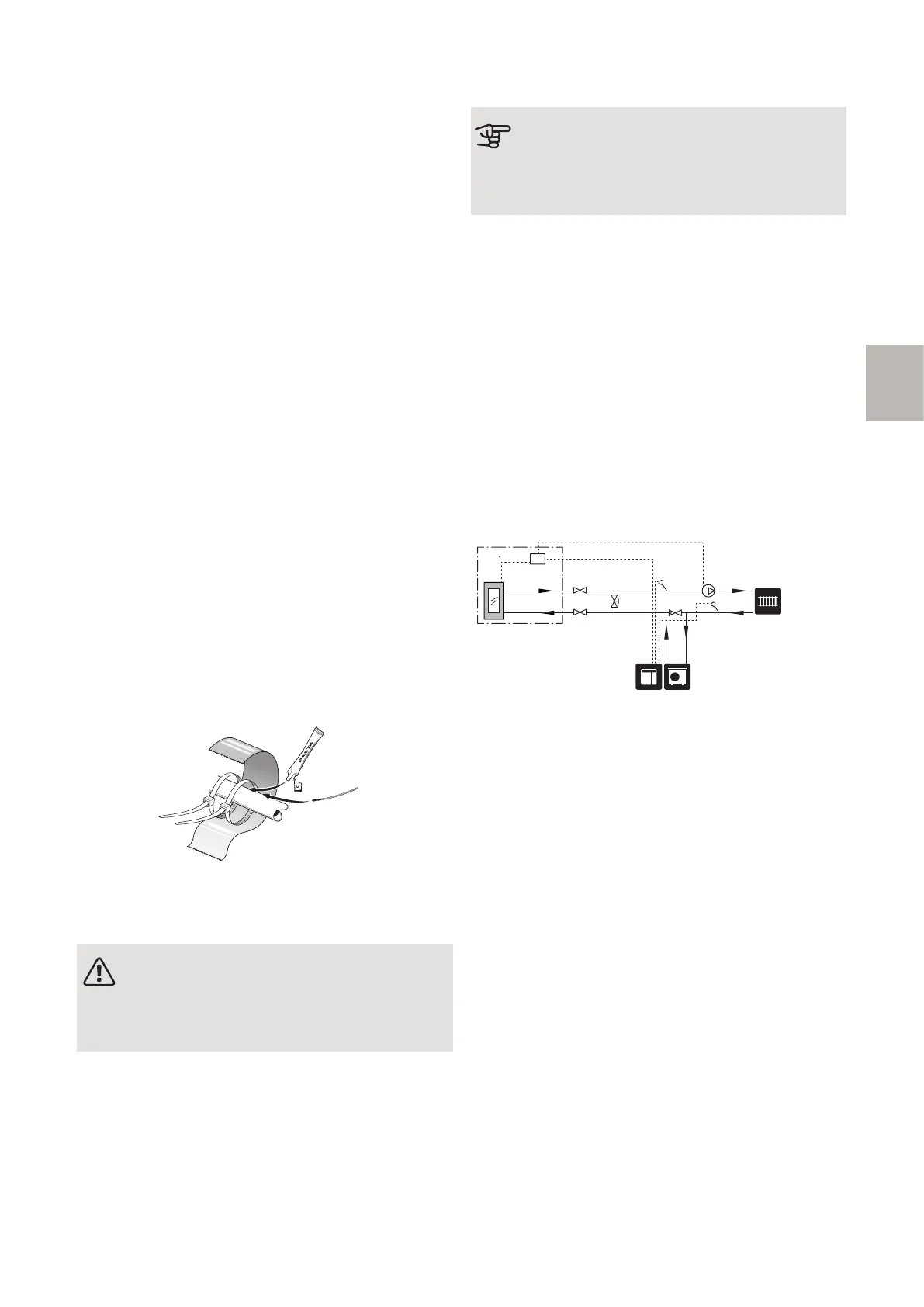
OUTLINE DIAGRAM WITH
STEP-CONTROLLED ADDITIONAL HEAT
-EB1
-GP10
-AA35
-
BT25
-RN1
-QM42
-QM43 -RM1
-
AA35
-AA35-BT71
13AXC 30 S-series | GB
S
 Loading...