Extra climate system
GENERAL
This function is used when SMO S40 is going to control
more than one climate system. It is possible to connect
up to eight different climate systems (heating and/or
cooling systems) that require different supply temperat-
ures, for example where the house has both radiator
systems and underfloor heating systems.
Caution
With underfloor heating systems, the maxim-
um supply temperature is normally set
between 35 and 45 °C.
Check the max floor temperature with your
floor supplier.
Caution
If a room sensor is used in a room with under-
floor heating, it should only have an indicatory
function, not control of the room temperature.
PIPE CONNECTIONS
GENERAL
When connecting extra climate systems, they must be
connected so that they have a lower working temperat-
ure than the climate system 1.
CIRCULATION PUMP
The extra circulation pump (EP21-GP10) is positioned in
the extra climate system according to the outline dia-
gram.
SHUNT VALVE
The shunt valve (EP21-QN25) is located on the supply
line after the heat pump/indoor module, before the first
radiator in the climate system 1. The return line from
the extra climate system is connected to the shunt valve
and to the return line from the climate system 1, see
image and outline diagram.
• Connect the supply line to the climate
system from the heat pump to port A on
the shunt valve (opens on increase signal)
• Connect the return line from the climate
system to port B on the shunt valve via
the T-pipe (closes on reduce signal).
• Connect the supply line to the climate system to the
common port AB on the shunt valve (always open).
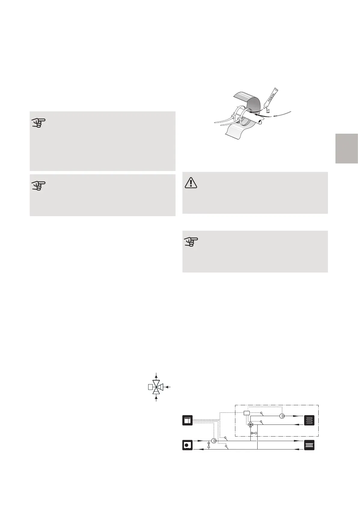
TEMPERATURE SENSOR
• The supply line sensor (EP21-BT2) is installed on the
pipe between the circulation pump (EP21-GP10) and
shunt valve (EP21-QN25).
• The return line sensor (EP21-BT3) is installed on the
pipe from the extra climate system.
Install the temperature sensors using cable ties, together
with the heat conducting paste and aluminium tape.
Then insulate with the enclosed insulation tape.
NOTE
To prevent interference, sensor cables to ex-
ternal connections must not be laid close to
high voltage cables.
SYSTEM DIAGRAM
Caution
This is an outline diagram. Actual installations
must be planned according to applicable
standards.
EXPLANATION
Climate systemEP21
AXC moduleAA25
Flow temperature sensor, extra climate
system
BT2
Return line sensor, extra climate systemBT3
Circulation pump, extra climate systemGP10
Shunt valveQN25
Non-return valveRM1
SMO S40AA35
External supply temperature sensorBT25
External return line sensorBT71
External heating medium pumpGP10
Non-return valveRM1.2
-EP21-RM1
-EP21-GP10-EP21-BT2
-EP21-AA25
-EP21-BT3
-EP21-QN25
-EP21
-AA35
-GP10
-AA35
-
AA35
-BT25
-AA35-BT71
-RM1.2
17AXC 30 S-series | GB
S
 Loading...