ELECTRICAL CONNECTION
NOTE
Read section "Common electrical connection"
for instructions regarding electrical connection.
CONNECTION OF SENSORS AND EXTERNAL
ADJUSTMENT
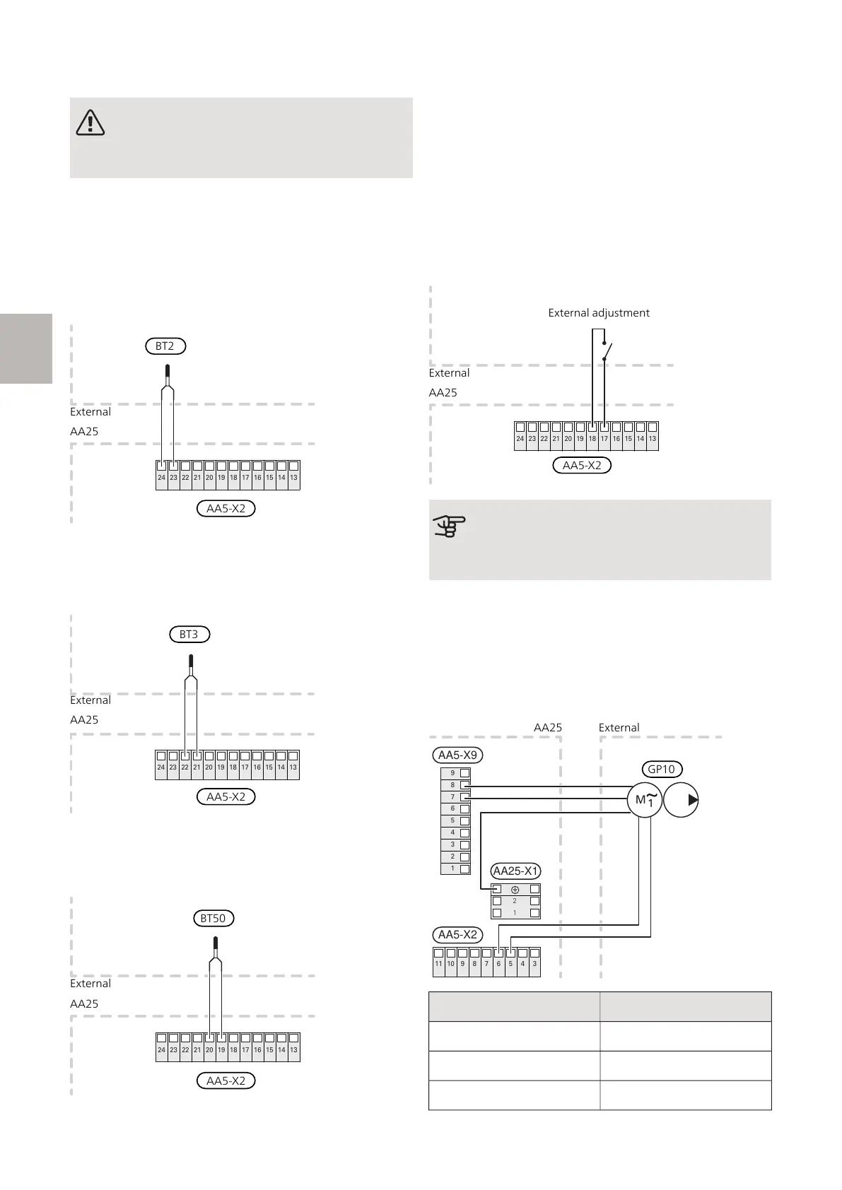
Supply temperature sensor, extra climate system
(EP21-BT2)
Connect the supply temperature sensor to AA5-X2:23-
24.
24 23 22 21 20 19 18 17 16 15 14 13
Return line sensor, extra climate system
(EP21-BT3)
Connect the return line sensor to AA5-X2:21-22.
24 23 22 21 20 19 18 17 16 15 14 13
Room sensor, extra climate system (EP21-BT50)
(optional)
Connect the room sensor to AA5-X2:19-20.
24 23 22 21 20 19 18 17 16 15 14 13
External supply temperature sensor (AA35-BT25)
Sensor (BT25) must be connected in the main product.
See the Installer Manual for the main product.
External return line sensor (AA35-BT71)
Sensor (BT71) must be connected in the main product.
See the Installer Manual for the main product.
External adjustment (optional)
A potential-free switch can be connected to AA5-X2:17-
18 for external adjustment of the climate system.
24 23 22 21 20 19 18 17 16 15 14 13
AA25
External
AA5-X2
External adjustment
Caution
The relay outputs on the accessory board can
have a max load of 2A (230V) in total.
CONNECTION OF THE CIRCULATION PUMP
(EP21-GP10)
Connect the external heating medium pump (GP10) to
AA5-X9:7 (N), AA5-X9:8 (230 V) and X1:PE.
Connect 0-10V control signal for heating medium pump
(GP10) to AA5-X2:5(0-10V) and AA5-X2:6(GND)
1
2
3
4
5
6
7
8
9
5 4 367891011
AA5-X9
AA5-X2
1
M
2
1
AA25-X1
Pump speed EP21-GP10
approx. 0 V DC100 %
approx. 5 V DC50 %
approx. 10 V DC0 %
AXC 30 S-series | GB18
S
 Loading...