In systems with cascade connection you determine in
the control system how many compressors are permit-
ted to work with pool heating.
An external heating medium pump (AA25-GP10)is re-
quired for the climate system, when one or more pools
are docked to the system, due to the fact that, during
pool charging, it is the charge pump (AA25-GP12) that
maintains the flow through the pool heat exchanger.
The external heating medium pump (AA25-GP10)
maintains the flow in the climate system, allowing the
external supply temperature sensor (AA25-BT25) to
measure the temperature correctly and allowing any
additional heat to be connected if necessary.
The pool’s circulation pump (CL11-GP9) circulates the
pool water between the pool exchanger and the pool.
The control module controls the reversing valve (CL11-
QN19), the pool circulation pump (CL11-GP9) and the
external heating medium pump (AA25-GP10) via AXC 30.
PIPE CONNECTIONS
REVERSING VALVE (CL11-QN19)
Install the reversing valve on the heating medium circuit,
which normally runs to a radiator system. One port goes
to the pool and one port goes to the heating system.
TEMPERATURE SENSOR
• The pool sensor (CL11-BT51) is placed on the return
line from the pool.
• The external supply temperature sensor (AA25-BT25)
is placed on the supply line to the climate system,
before the external heating medium pump (AA25-
GP10) .
• The external return line sensor (AA25-BT71) is placed
on the return line from the climate system.
Install the temperature sensors using cable ties, together
with the heat conducting paste and aluminium tape.
Then insulate with the enclosed insulation tape.
NOTE
To prevent interference, sensor cables to ex-
ternal connections must not be laid close to
high voltage cables.
FUNCTION
Heating of the pool is prioritised according to selected
settings in the control module. If the pool sensor (CL11-
BT51) is not connected, pool charging is not permitted
to start. The heating medium flow is adjusted so that
the temperature difference across the pool heat ex-
changer is 10–15 °C. This setting is made in menu 5.1.11
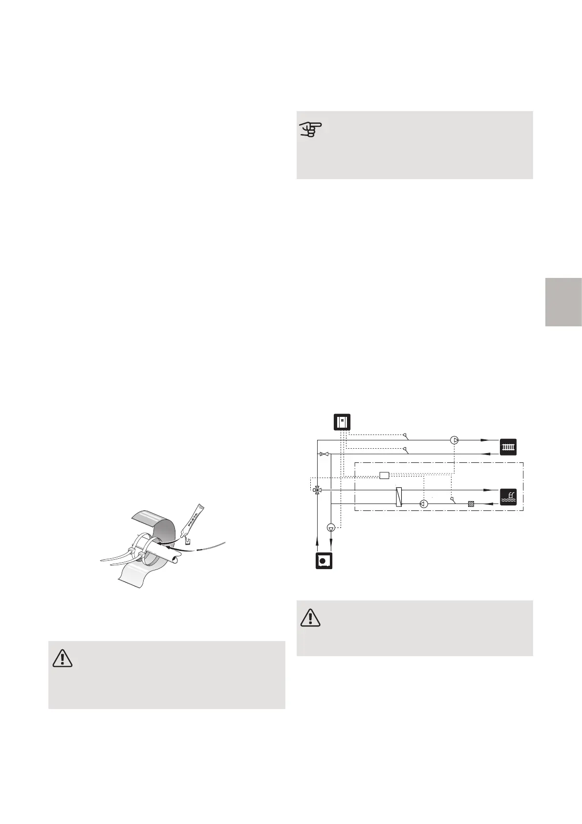
SYSTEM DIAGRAM
Caution
This is an outline diagram. Actual installations
must be planned according to applicable
standards.
EXPLANATION
Pool heatingCL11
AXC 30AA25
Three way valve, poolQN19
Pool heat exchangerEP5
Circulation pump, pool circuitGP9
Temperature sensor, poolBT51
Particle filterHQ4
Heat pumpEB101
Control moduleAA25
External heating medium pumpGP10
External supply temperature sensorBT25
External return line sensorBT71
Charge pumpGP12
Miscellaneous
Non-return valveRM1
-AA25-GP10-AA25-BT25
-RM1
-EB101
-AA25-BT71
-AA25
-AA25
-GP12
-CL11-HQ4-CL11-BT51-CL11-GP9
-CL11-EP5
-CL11-AA25
-CL11
ELECTRICAL CONNECTION
NOTE
Read section "Common electrical connection"
for instructions regarding electrical connection.
73AXC 30 F-series | GB
F