Do you have a question about the Nibe ECS 41 and is the answer not in the manual?
Covers safety guidelines, symbol explanations, and product marking for the S-series.
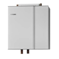
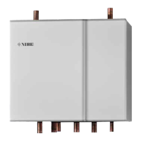
Details product description, compatible units, and package contents for the S-series.
Explains installation principles and general guidelines for connecting extra climate systems.
Provides instructions for installing the shunt valve and temperature sensors.
Details pump overview, LEDs, and available operational settings.
Explains Proportional Pressure Auto Adapt (PPAA) and Constant Pressure Auto Adapt (CPAA) modes.
Details Constant Pressure (CP) and Constant Curve (CC) pump control modes.
Describes common alarm causes and their corresponding LED indications.
Presents wiring diagrams and explains symbols used in the manual.
Covers electrical connection safety precautions and AXC module mounting.
Guides on connecting communication to control modules and heat pumps.
Details connections for supply/return sensors, room sensor, and external adjustment.
Shows configuration of the accessory board's DIP switch for climate systems.
Explains start guide, menu system access, and temperature/room sensor configurations.
Covers setting heating/cooling curves and minimum supply temperatures.
Lists technical specifications for the AXC module, including electrical data and dimensions.
Covers safety guidelines, symbol explanations, and product marking for the F-series.
Details product description, compatible units, and package contents for the F-series.
Explains installation principles and alternative connection methods for F370/F470.
Provides instructions for installing the shunt valve and temperature sensors.
Details pump overview, LEDs, and available operational settings.
Explains Proportional Pressure Auto Adapt (PPAA) and Constant Pressure Auto Adapt (CPAA) modes.
Details Constant Pressure (CP) and Constant Curve (CC) pump control modes.
Describes common alarm causes and their corresponding LED indications.
Presents wiring diagrams and explains symbols used in the manual.
Covers electrical connection safety precautions and AXC module mounting.
Details communication and power connections for F1345 versions.
Details connections for supply/return sensors, room sensor, and external adjustment.
Shows configuration of the accessory board's DIP switch for climate systems.
Explains start guide, menu system access, and system/accessory settings.
Lists technical specifications for the AXC module, including electrical data and dimensions.
| Brand | Nibe |
|---|---|
| Model | ECS 41 |
| Category | Temperature Controller |
| Language | English |