EasyManua.ls Logo

Nibe PCM 40 User Manual

Nibe PCM 40
52 pages
Go to English
To Next Page IconTo Next Page
Page #1 background imageLoading...
Page #1 background image
LE
K
PCM 40/42
SE
Installatörshandbok Passiv kyla
GB
Installer manual Passive cooling
DE
Installateurhandbuch Passive Kühlung
NL
Handleiding voor installateur Passieve koeling
IHB 1704-2
331733
Question and Answer IconNeed help?

Do you have a question about the Nibe PCM 40 and is the answer not in the manual?

Nibe PCM 40 Specifications

General IconGeneral
CategoryTemperature Controller
ManufacturerNibe
ModelPCM 40
Power supply24 V AC/DC
Protection classIP20
CommunicationModbus RTU
Storage temperature range-20°C to +70°C
Relative humidityMax. 95 % RH
Analog input type0-10 V DC or 0(4)-20 mA
Digital input typeDry contact

Summary

Important Information and Warnings

General System Overview

Mounting Instructions

Heating and Cooling Operation Modes

Cooling Module Design Details

Electrical Connection Guide

Hydraulic and Brine Pipe Connections

Expansion Vessel Requirements

System Outline Diagrams

Circulation Pump Speed Adjustment

Post-Installation Venting Procedure

System Alarm Indicators

Performance Data Charts

Pressure Drop Analysis

Electrical Connection Safety Notes

Connecting Communication Systems

Accessory Board and Sensor Connections

Program Settings

Start Guide and Menu System Access

How to access and use the initial setup guide and the main menu system.

Accessory Activation

Configuring system settings to activate or deactivate accessories.

Cooling Configuration

Adjusting parameters for passive cooling operation.

Input/Output and Control Settings

Configuring sensors, inputs, outputs, and forced control of components.

Technical Data and Specifications

Dimensions Overview

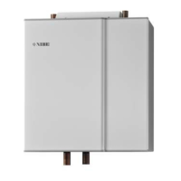
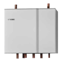
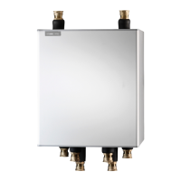
Physical dimensions of the PCM 40 and PCM 42 units.

Key Technical Specifications

Key technical parameters including connections, weight, and output.

Wiring Diagram and Connections

Communication and Dip Switch Configuration

Wiring for communication and setting dip switches for operation.

Control and Component Wiring

Wiring details for sensors, relay outputs, and control valves.

Related product manuals