Pipe connections
General
When connecting extra climate systems, they must be
connected so that they have a lower working temper-
ature than the climate system 1.
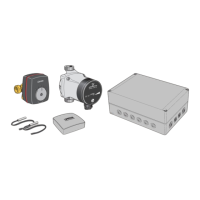
Circulation pump and mixing valve
The extra circulation pump (GP20) is positioned in the
extra climate system according to the outline diagram.
F1145/F1155/F1245/F1255/F1345/F750/
VVM310/VVM320/VM500/SMO40
႑
The mixing valve (QN25) is located on the flow line
after the heat pump/indoor module, before the first
radiator in the climate system 1. The return line from
the additional climate system must be connected to
the shunt valve and to the return line from the heat-
ing system 1, see image and outline diagram.
F370/F470
႑
First drain the boiler water reservoir/heating system
if filled with water.
႑
Unscrew the plugged connection that is on the
docking connection (XL8).
႑
Install the supplied plastic pipe with coupling in the
docking connection (XL8).
႑
The mixing valve (QN25) is located on the flow line
after the heat pump from its docking connection
(XL8). The return line from the extra climate system
is connected to the mixing valve and to the return
line from the heating system 1, see image and outline
diagram.
NOTE
Incorrect installation can affect the function.
By-pass valve, (QN25)
Connections, Ø 22 mm
LEK
LEK
Return
Heat pump/
indoor module
Flow pipe
Temperature sensor
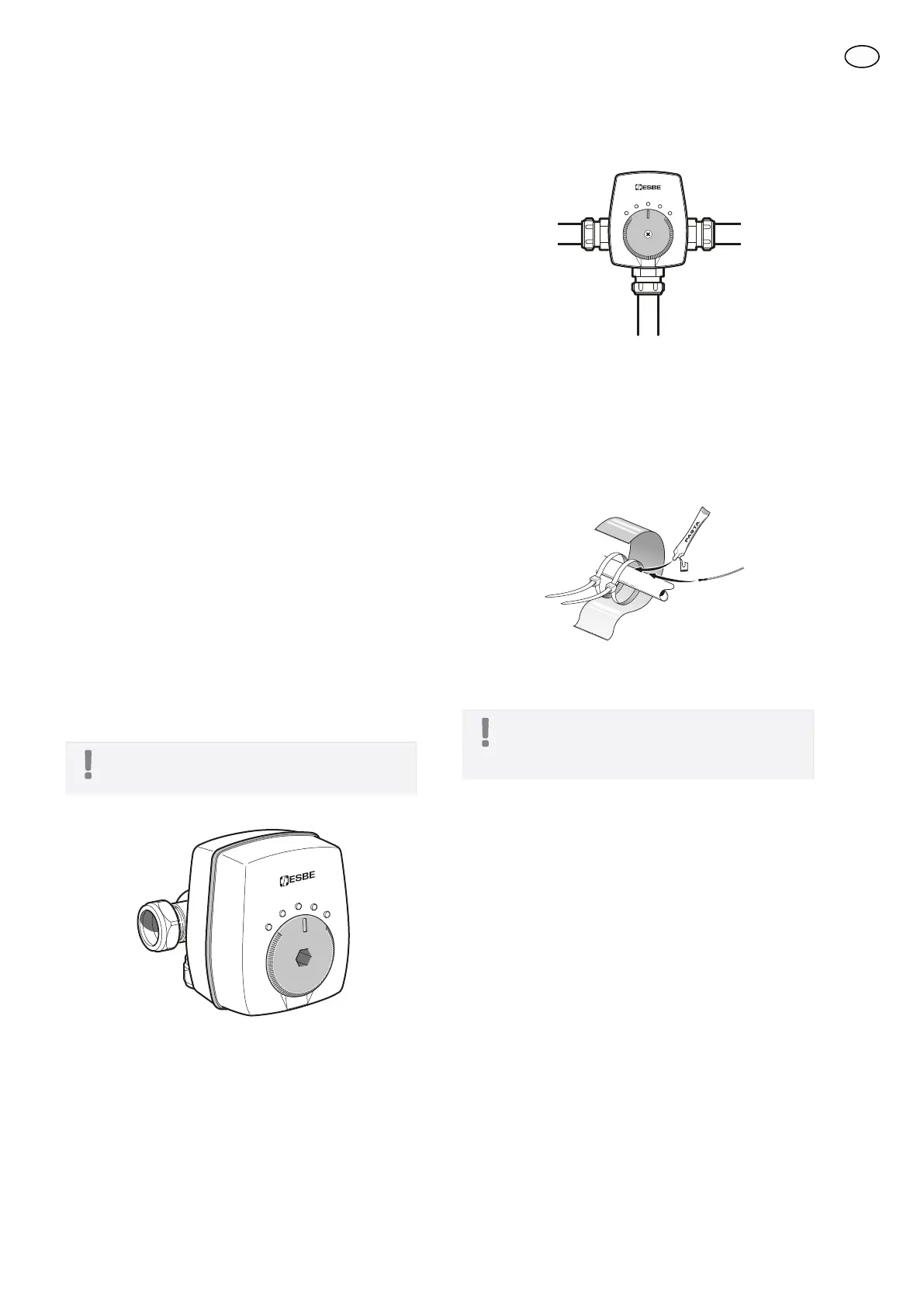
႑
The flow temperature sensor (BT2) is installed on the
pipe between the circulation pump (GP20) and mix-
ing valve (QN25).
႑
The return line sensor (BT3) is installed on the pipe
from the extra climate system.
Install the temperature sensors with cable ties with the
heat conducting paste and aluminium tape. Then insu-
late with supplied insulation tape.
NOTE
Sensor and communication cables must not
be placed near power cables.
19
GB
 Loading...