Pipe installation
7
FLM 30
For the Installation engineer
The condensation water hose is routed directly to the
floor drain or other water seal. Ensure that the end of
the hose runs out above the water level in the floor
drain. The pipe installation must be carried out in ac-
cordance with current norms.
Output transfer to
brine
FLM 30 is filled from the heat pump's brine, see the
Installation and Maintenance instructions in question.
Vent using the venting screw (5). The switch (38)
should be set to “0”. when venting
SF
Brine in
Brine out
C
i
r
k
.
p
u
m
p
V
ä
r
m
e
p
u
m
p
V
a
r
m
v
a
t
t
e
n
T
i
l
l
s
a
t
s
v
ä
r
m
e
L
a
r
m
K
o
n
t
r
o
l
l
e
r
a
a
t
t
v
a
t
t
e
n
f
i
n
n
s
i
p
a
n
-
n
a
n
i
n
n
a
n
d
e
n
i
n
-
k
o
p
p
l
a
s
.
1
R
0
SÄV
FLM 30
Exhaust air
Ø 160
Extract air
Ø 160
EXP
BV
RV
P
EXP
Pressure expansion vessel
According to the
recommendations
SÄV Safety valve
BV Check valve Included in FLM 30
SF Particle filter
RV Trim valve Included in FLM 30
P Pressure gauge
The brine circuit should be fitted with a pressure ex-
pansion
vessel. If there is a level vessel this should
be replaced. The brine
side should be pressurised to
at least 0.5 bar.
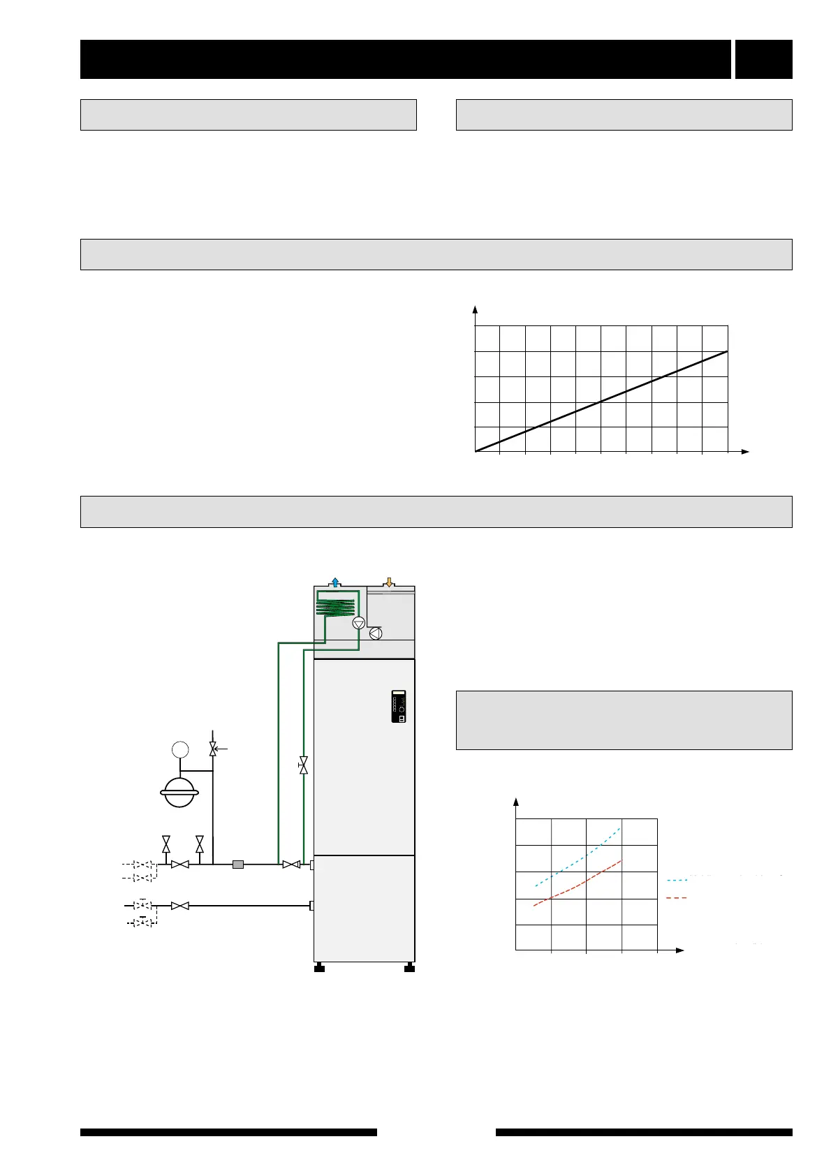
The pressure expansion vessel should be dimen-
sioned as set out in the diagram, to prevent operating
disturbances. The pressure expansion vessel covers
the temperature range from -10 °C to +20 °C at a pre-
pressure of 0.5 (bar) and the safety valve’s opening
pressure 3 bar.
0
0
l
100
200
l
300
10
20
30
Pressure expansion vessel
Brine
volume
40
50
400
500
600
700
800
900
1000
The lowest permitted incoming brine temperature is -
5 °C.
When installing on FIGHTER 1210 the space under
FLM 30 is limited to 90 mm. This may mean that the
pipe connections on FIGHTER 1210 must be short-
ened.
The brine is connected to FLM 30 as set out on the
outline diagram.
0
100
(m
3
/h)
300
0,5
1
1,5
Överförd effekt (kW)
Luftflöde
2
2,5
500
200
400
Köldbärare in vid 0 °C
Köldbärare in vid 5 °C
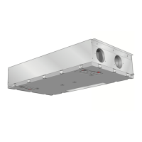
The diagram shows the effect transferred from the
ventilation air to the brine and applies for an air tem-
perature of +20 °C and 50% relative air humidity.
Transferred effect (kW)
Air flow (m
3
/h)
Brine in at 0 °C
Brine in at 5 °C
Pipe connections (brine)
Condensation water hose
Pressure expansion vessel
Filling and venting the system