3
3.1 - Connecting the motor to the mains power
supply
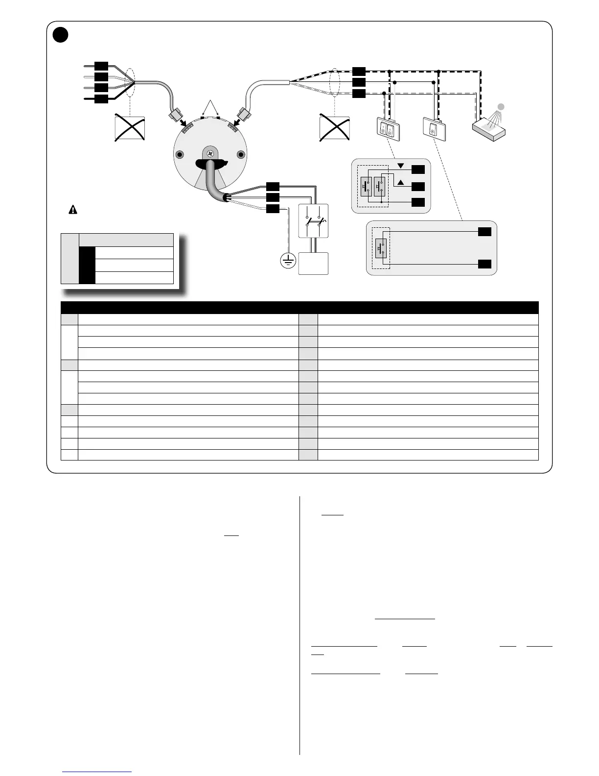
The motor is powered by a permanent connection to the mains. Use cable “A” (fig.
3) for this connection, making sure to observe the warnings in full.
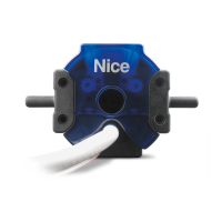
3.2 - Connecting accessories and sensors
Only cabled accessories and climate sensors can be connected to the mo-
tor. For such connections use cable “B”, referring to fig. 3 and the following in-
structions.
– You can connect only one compatible accessory at a time to the white and
white-black cables.
– You can connect only one compatible accessory at a time to the white-orange
and white-black cables.
– Up to 5 tubular motors can be connected to one accessory, respecting the polar-
ity of the signals (connect the white-black cables of all motors together as well as
the white-orange cables of all motors).
3.2.1 - Connecting push button panels
You can connect either 1 or 2 button panels.
Caution! - The maximum length of the cables used to connect a wall-mounted pan-
el or a relay is 100 m.
– Model with 1 button excites an input: the command is either Open or Step-by-
step; the command is memorised with procedure A.7. The panel must be connect-
ed to the white and white-black wires.
– Model with 2 buttons excites two inputs: one for the Up command, and one for
the Down command; it is also possible to program the operating logic using pro-
cedure A.5. The Open and Close inputs are constrained to reach other, in other
words they must be used with the same pushbutton panel (fig. 3).
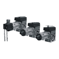
3.3 - Connecting the motor to the DMBM module
To connect the motor to the DMBM module, use cable “C” and refer to fig. 3.
LEGEND
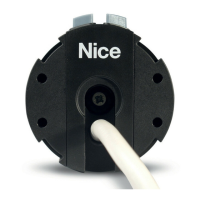
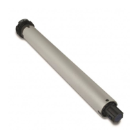
A Power cable D Electronic motor head
A1 = Brown wire E Limit switch adjustment buttons
A2 = Blue wire 1 Double button
A3 = White-orange wire 2 Single button (“Open” or “Step-by-Step” command)
B Command cable 3 Climate sensor (wired)
B1 = White wire 4 Motor mains power disconnector.
B2 = White-orange wire 5 Connection to the mains
B3 = White-black wire 6 Earth connection
C Smart-Bus cable
C1 = Red wire
C2 = Yellow wire
C3 = Blue wire
C4 = Black wire
EN USA (UL)
A A1
White
A2
Black
A3
Green/
Yellow-green
**
*
DRY CONTACT
** THE POWER CABLE IS REMOVABLE
* *