English – 10
EN
has 10 seconds for entering consecutive digits; after this time
has elapsed, the combination will have to be re-entered start-
ing from the beginning.
l
During the automation’s operation,
the “L2” LED emits light signals. Consult Table 6 for explana-
tions on their meaning.
10 - TESTING
Once programming is completed, it is necessary to verify
whether the device functions properly, in the following way.
IAI Verify that the instructions specified in Chapter 1 - “Gen-
eral warnings and precautions” have been observed. IBI Read
Chapter 9 for instructions on how to use the device correctly.
ICI Enter a valid combination on the keypad and press the
command button associated with the combination. Sub-
sequently, observe ... • the signal emitted by the “L1” LED
and consult Table 5 for its interpretation; • the signal emitted
by the “L2” LED and consult Table 6 for its interpretation;
• the command performed by the automation. If the obser-
vations and interpretations just carried out are contradictory,
read Chapter 11 - “Troubleshooting”. IDI Perform the check
described in the previous point, for each of the other stored
combinations.
11 - TROUBLESHOOTING
l
The “L2” LED emits 2 flashes + pause, red. Check
behind the keypad to verify whether the jumper is properly
inserted.
l
(
Presence of multiple keypads connected to the same
control unit). After transmitting a command, if the lat-
ter is not performed and the “L2” LED fla
shes 3 times
+ pause. Ensure that each keypad has the jumper in-
serted in a different position to those used by the other
“BlueBus” control devices present in the installation.
l
No buzzes are heard when pressing the keypad but-
tons.
Check that the BM memory is properly inserted.
l
After transmitting a command, if the “L1” LED flash-
es to signal that the command has been transmitted,
but the control unit has actually not carried it out.
Check that device recognition procedure performed by the
control unit has been correctly executed.
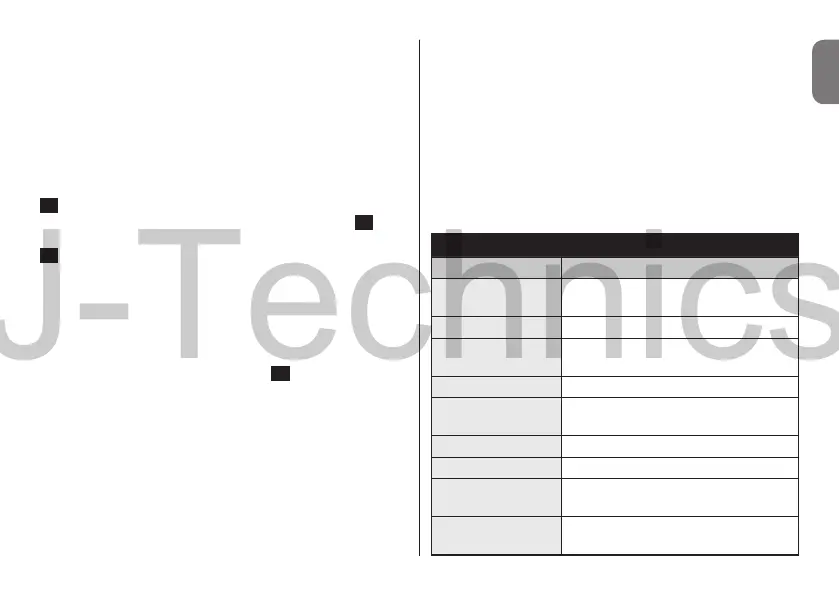
TABLE 6 - “L2” LED signals
“L2” LED signal Meaning
RED stable lit
Gate closed and automation
unlocked
RED stable lit Gate in closing phase
RED stable lit
Gate not closed nor open and
automation unlocked
GREEN stable lit Gate in opening phase
GREEN stable lit
Gate not closed nor open and
automation locked
GREEN stable lit Gate open and automation locked
GREEN stable lit Gate closed and automation locked
RED (3 ashes +
1 pause)
Device non synchronised on
“BlueBus”
RED (2 ashes +
1 pause)
Device not addressed (i.e. without
jumper)