English – 11
English
Ø = 6 mm
x4
05. B
Ø = 6 mm
x4
05. A
2
1
(aerial)(flash)
2
1
06. 07.
08. 09.
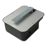
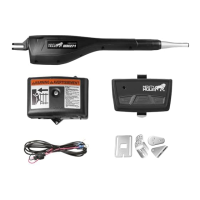
6.2 - INSTALL AND CONNECT FL200 FLASHING
INDICATOR (fig. 26)
• The flashing light must be positioned near the gate in a clearly
visible position. It can be fasted to a horizontal or vertical surface.
• For connection to the Flash terminal, no polarity needs to be observed;
instead for connection of the shielded aerial cable, it is necessary to con-
nect the cable and sheath as shown in Fig. 22.
Choose the most suitable position in which to install the flashing light: it
must be positioned near the gate in a clearly visible position. It can be
fasted to a horizontal or vertical surface.
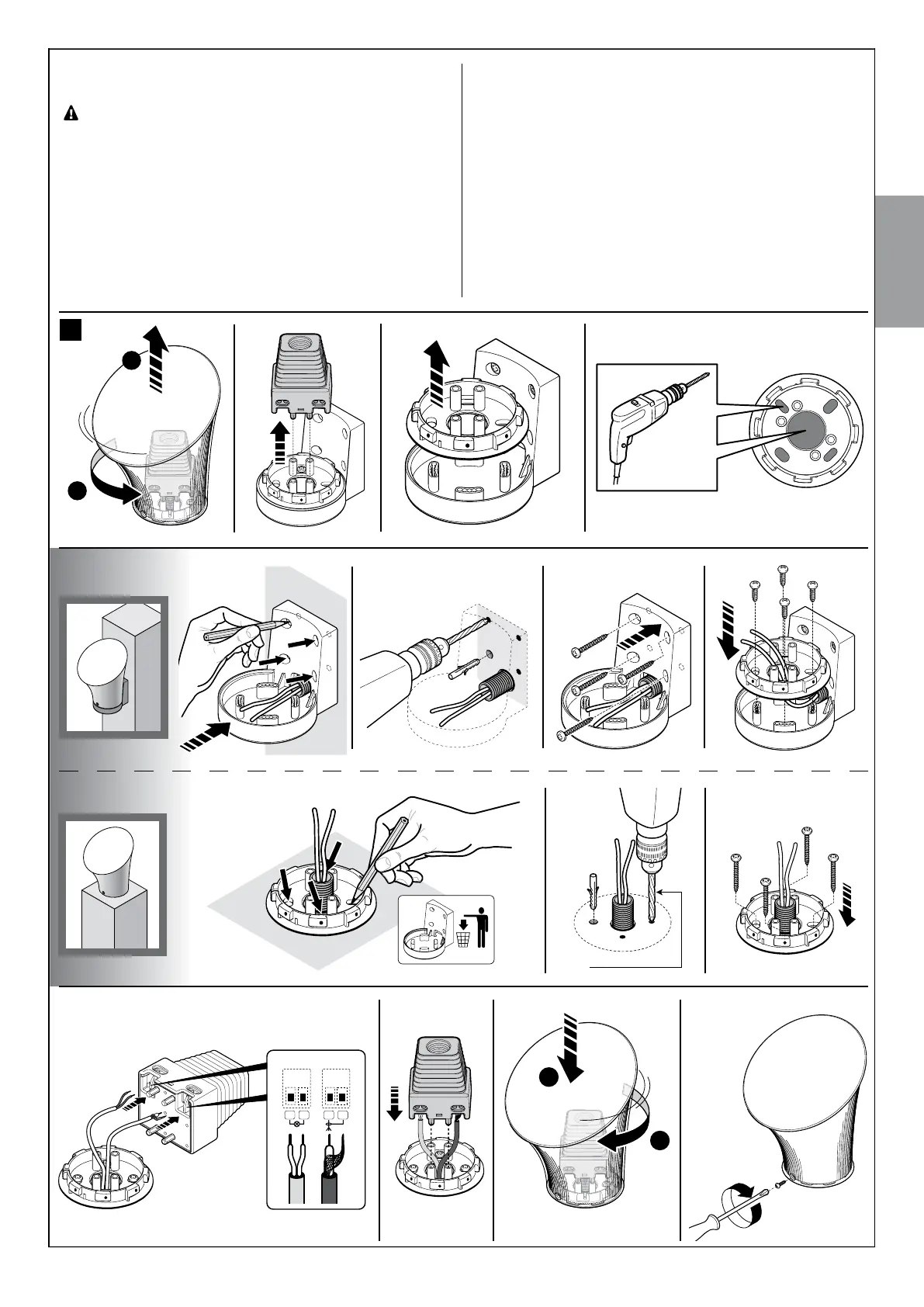
For the installation procedure see Fig. 26.
02. 03. 04.01.
26
 Loading...