English – 25
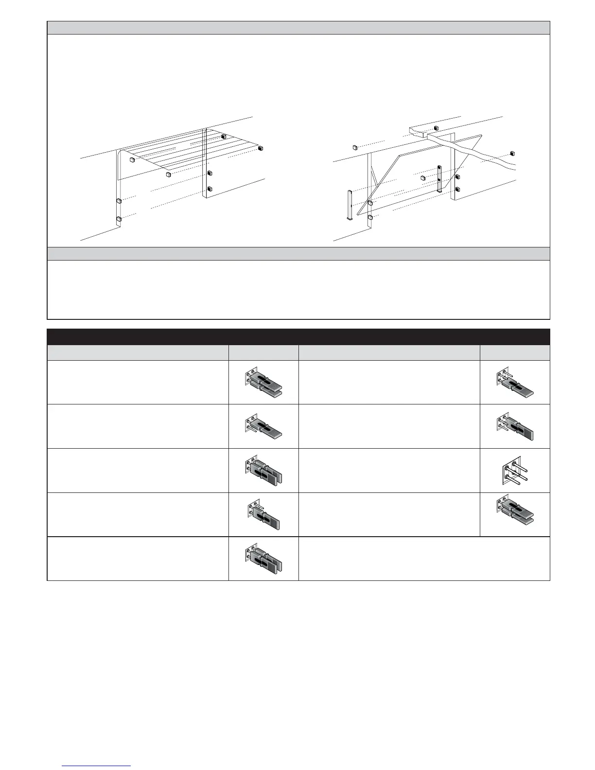
Photocells
By means of addressing using special jumpers, the “BlueBUS” system enables the user to make the control unit recognise the photocells and
assign them with a correct detection function. The addressing operation must be done both on TX and RX (setting the jumpers in the same
way) making sure there are no other couples of photocells with the same address. In an automation mechanism for sectional or non-protruding
overhead doors, it is possible to install photocells as shown in Table 18. In an automation for protruding overhead doors, refer to the following
jFTQD
Photo 2 and Photo 2II are used in special installations requiring complete protection of the automation, also during opening. After the installa-
tion or removal of photocells, the recognition phase in the control unit as described in Paragraph 7.1 must be carried out.
F
OTO 2
FOTO 2 II
FOTO II
F
OTO
FOTO 2
FOTO 1 II
FOTO II
FOTO
FO
T
O 1
FOT
O 2 II
BlueBUS
BlueBUS technology allows you to connect compatible devices using only two wires which carry both the power supply and the communi-
cation signals. All the devices are connected in parallel on the 2 wires of the BlueBUS itself. It is not necessary to observe any polarity; each
device is individually recognized because a univocal address is assigned to it during the installation. Photocells, safety devices, control keys,
signalling lights etc. can be connected to BlueBUS The SPIN control unit recognizes all the connected devices individually through a suitable
recognition process, and can detect all the possible abnormalities with absolute precision For this reason, each time a device connected to
BlueBUS is added or removed the control unit must go through the recognition process; see paragraph 8.2.
Table 18 - Photocell addressing
Photocell Jumpers Photocell Jumpers
PHOTO
External photocell h = 50
activated when door closes
invert in opening
PHOTO 2
External photocell
activated when door opens
invert in closing
PHOTO II
External photocell h = 100
activated when door closes
invert in opening
PHOTO 2 II
Internal photocell
activated when door opens
invert in closing
PHOTO 1
Internal photocell h = 50
activated when door closes and opens
temporary stop and invert in “open”
PHOTO 3
Single photocell
with activation during opening and closing (tem-
porary stop and reverses in “open”)
PHOTO 1 II
Internal photocell h = 100
activated when door closes and opens
temporary stop and invert in “open”
FA1
Photocell for opening command
(cut jumper A on the back of the TX and RX cards)
FA2
Photocell for opening command
(cut jumper A on the back of the TX and RX cards)