PC Board Quick References
Manual # 42-02-1P28 A3 6-7
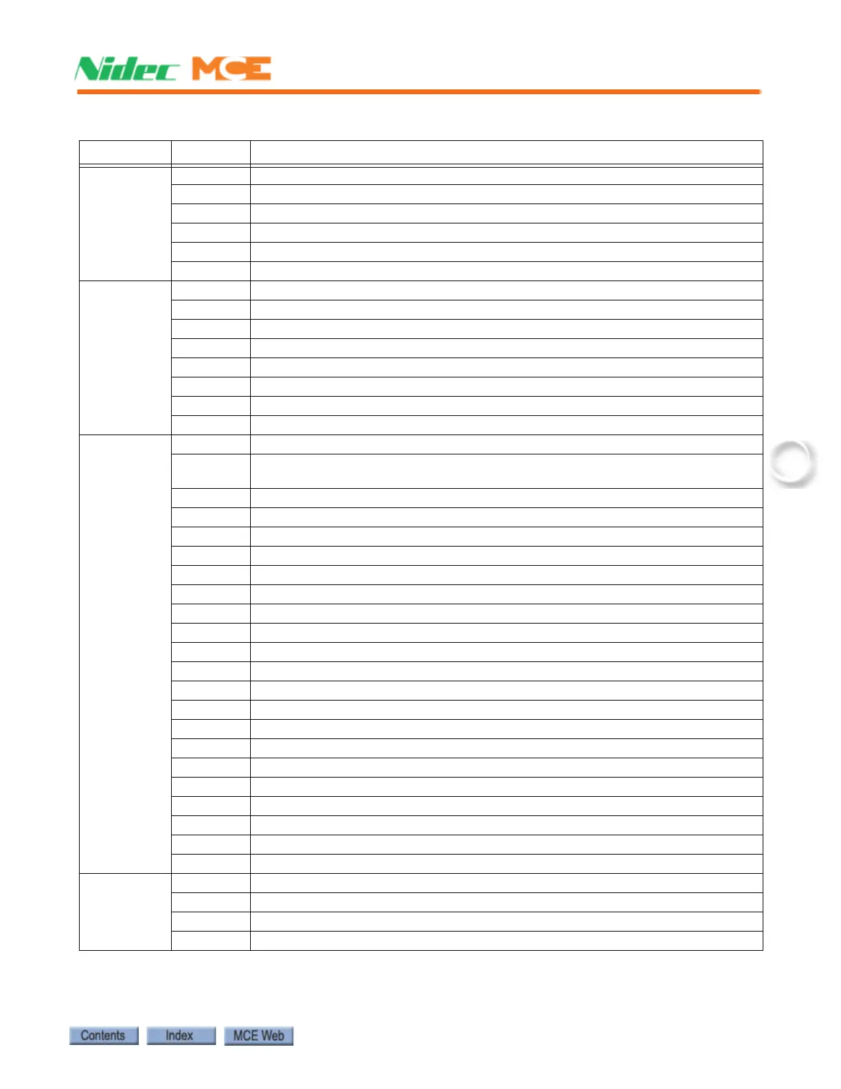
J10
MCE wired
at factory.
Not for field
connection.
ICTD See description, connector J27
ICTU See description, connector J27
CTEN See description, connector J27
INCT See description, connector J27
FRS See description, connector J27
FRA See description, connector J27
J11
MCE wired
at factory.
Not for field
connection.
ABD See description, connector J27
ABU See description, connector J27
ATD See description, connector J27
ATU See description, connector J27
INA See description, connector J27
INN See description, connector J27
INCP See description, connector J27
ICEN See description, connector J27
J12 GSR Gate switch rear (rear opening car gate switch made input)
DCABR
Door contact access bottom rear (bottom access floor rear door contact made
input)
DLABR Door lock access bottom rear (bottom access floor rear door lock made input)
DLMS Door lock middle string (floors between access floors, contacts made input)
DLAT Door lock access top (top access floor door lock made input)
DZF Front door zone input, discrete landing system connection
DZR Rear door zone input, discrete landing system connection
LIM0 Used with hydro applications only
LIM1 Used with hydro applications only
LIM2 Used with hydro applications only
LIM3 Used with hydro applications only
GS Gate switch (car gate switch made input)
DCAB Door contact access bottom (bottom access floor door contact made input)
DLAB Door lock access bottom (bottom access floor door lock made input)
DCMS Door contact middle string (floors between access floors, contacts made input)
DCAT Door contact access top (top access floor door contact made input)
SAFH Safety string, hoistway (input)
SAFC Safety string, car (input)
ESC In-car stop switch bypass (completes SAFC safety string with switch open)
SPD0 Speed bit from LS-EDGE landing system sensor
SPD1 Speed bit from LS-EDGE landing system sensor
SPD2 Speed bit from LS-EDGE landing system sensor
J14 SPOUT1 Programmable spare output #1. Defined on job prints if used.
SPOUT2 Programmable spare output #2. Defined on job prints if used.
SPOUT3 Programmable spare output #3. Defined on job prints if used.
SPOUT4 Programmable spare output #4. Defined on job prints if used.
Table 6.2 HC-CTL-2 Board Terminals
Connector Terminal Description