Troubleshooting
6-12 Manual # 42-02-1P28 A3
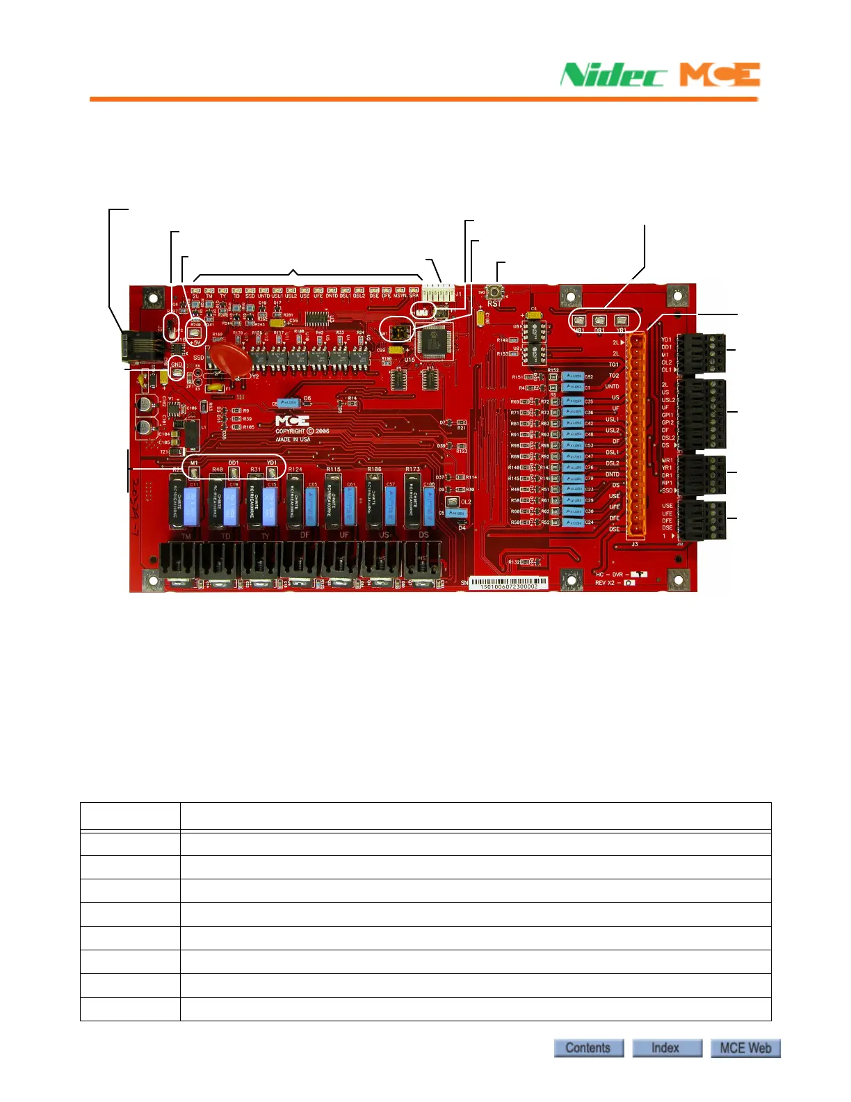
HC-DVR Driver Board
The HC-DVR Driver board control the pumps and valves.
Figure 6.4 HC-DVR Driver Board
Switches
• SW1: Board ID. DVR #1: 1 = Off, 2 = Off. DVR #2: 1 = On, 2 = Off. DVR #3: 1 = Off, 2 = On.
• SW2: RST - Processor reset.
Jumpers
• JP1: Processor hard reset - Open. Jumper required only to perform 2K compliance testing.
• JP2: Internal CAN network termination - Open.
Table 6.7 HC-DVR Board Test Points
Test Point Description
+5V +5 Vdc measured between this test point and TP GND.
DD1 TD triac output test point
DR1 Delta contactor monitor input test point
GND 0 volts
M1 TM triac output test point
MR1 Main contactor monitor input test point
YD1 TY triac output test point
YR1 Wye contactor monitor input test point
J2: Internal CAN connection
JP2
Indicators
J10
J3
J13
J11
J12
J1
SW2: RST
TP MR1
TP DR1
TP YR1
TP +5V
JP1
SW1
TP M1
TP DD1
TP YD1
GMND
TP GND