PC Board Quick References
Manual # 42-02-1P28 A3 6-21
HC-UIO-2 Switch Settings (7, 8, and 9)
On the HC-UIO-2 Board switches 7 and 8 set the baud rate at which the CAN bus communicates
with this board.
On the HC-UIO-2 Board switch 9 sets the activation threshold for inputs I/O1 through I/O16..
HC-UIO-2 Used for Calls
When HC-UIO-2 boards are used for hall or car calls, the brightness of the LEDs associated
with inputs and outputs has significance.
Level o - LED Off
• The input is not active and the output is not latched on.
Level 1 - LED medium brightness
• The input is not active and the output is latched on.
Level 2 - LED full brightness
• The input is active and the output may or may not be latched on.
LED flashing
• Maximum continuous current draw exceeded (overload or short detected).
Hospital Emergency Operation I/O
I/O 1 through I/O 4 on UIO-2 Board #16 are used for hospital emergency operation connec-
tions HEO, HWI, HSEL, and HOSPH2 respectively.
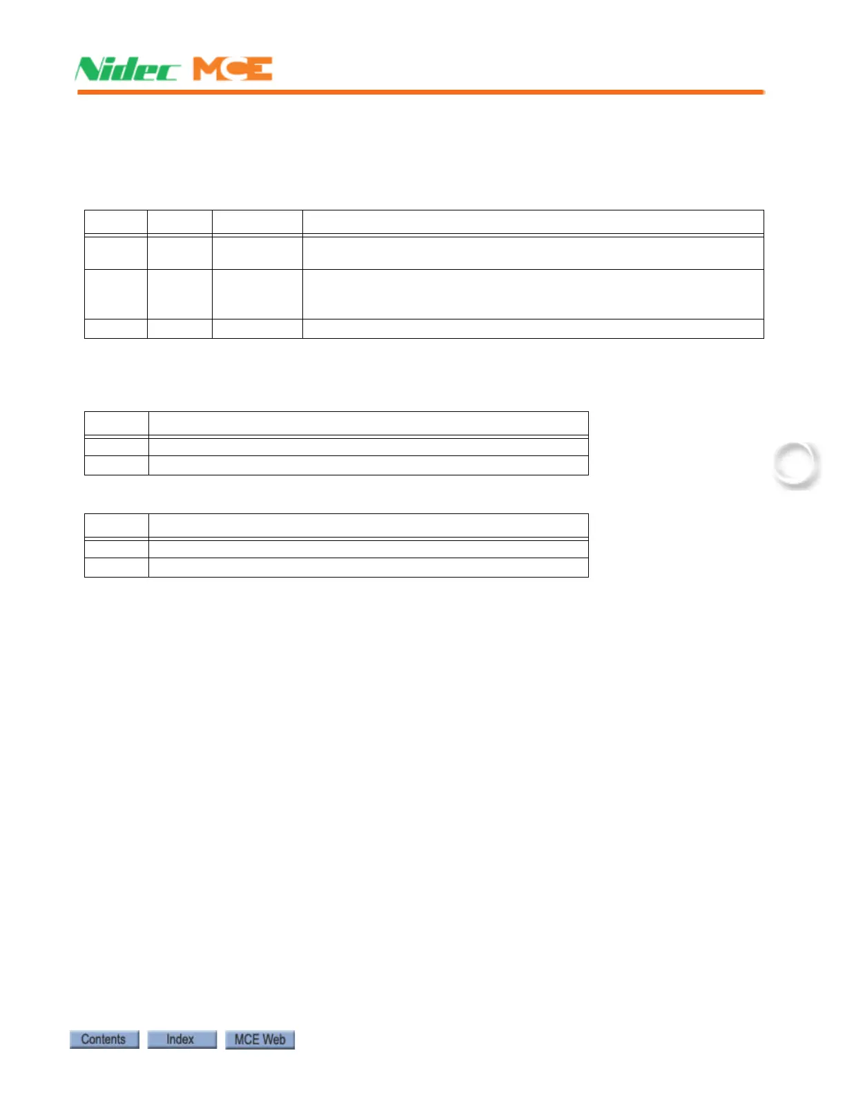
Table 6.16 HC-UIO-2 Board Switches 7 and 8
Sw 7 Sw 8 Baud Rate Description
OFF OFF 500 kbps
For boards inside the controller, RJ12 cable from J2 on HC-UIO-2 board
to HC-CHP board Internal Network J1 through J10.
ON OFF 250 kbps
For boards on the cartop, RJ12 cable from J2 on HC-UIO-2 board to MC-
LSI board LAN connectors. Caution: Do not connect to J3 on the MC-LSI
(Landing System) board.
OFF ON 125 kbps Future use
Table 6.17 HC-UIO-2 Board Switch 9 for I/O Boards
Sw 9 Description
OFF Sets Input activation threshold to 18 Volts ac or dc
ON Sets Input activation threshold to 55 to 65 Volts ac or dc
Table 6.18 HC-UIO-2 Board Switch 9 for Call Boards
Sw 9 Description
OFF Sets Input activation threshold to 0.6 Volts ac or dc
ON Sets Input activation threshold to 0.2 Volts ac or dc