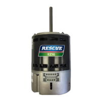
The RESCUE® EZ16™ Motor is an electrically commutated motor (ECM) designed as a drop-in replacement solution for HVAC and ventilation systems that utilize legacy 16-Pin controls. This motor aims to meet the growing demand for high-efficiency and precise airflow control in a wide array of air-moving applications. Its design incorporates Nidec's extensive ECM experience and offers comprehensive application support.
Function Description
The primary function of the RESCUE® EZ16™ Motor is to provide efficient and controlled air movement within HVAC and ventilation systems. It replaces existing ECM motors, particularly those with 16-Pin controls, offering an upgraded solution with enhanced features. The motor operates as a direct-drive centrifugal blower, meaning it is intended to be directly connected to a blower wheel to move air. It is designed for continuous, air-over duty, which necessitates its mounting within the air stream of an air-moving device, such as a fan. Operating the motor outside of the air stream can lead to overheating and potential damage.
The motor's operation is managed through an EZ Interface (EZI), which allows for field adjustments and communication with the HVAC system. This interface facilitates the configuration of various operating parameters, ensuring compatibility and optimal performance within different system setups. The EZI processes input signals from the HVAC system, translating them into precise motor control commands to regulate airflow and speed.
Usage Features
The RESCUE® EZ16™ Motor offers several features that enhance its usability and adaptability in various HVAC applications:
- Drop-in Replacement: Designed to seamlessly replace existing motors, simplifying the upgrade process for technicians.
- Field Adjustable: Key operating parameters can be adjusted in the field, allowing for customization to match specific system requirements.
- Dual Voltage Capability: The motor can operate on either 115 Vac or 208-230 Vac, providing flexibility for different electrical systems.
- Flexible Control Methods: Supports multiple control methods, including 24 Vac or PWM (Pulse Width Modulation) inputs, to integrate with a wide range of HVAC control systems.
- Selectable Rotation: The motor's rotation direction (CCW/CW) can be selected, ensuring proper airflow for different blower configurations. This is particularly important for 24VAC applications. In PWM mode, the motor employs rotation sensing technology during initial power-up, running for approximately 20 seconds in each direction to determine and store the correct rotation. This sensing process repeats if power is lost for more than 60 seconds.
- Adjustable Airflow: The EZI features dials for adjusting airflow settings for both cooling (Y1/Y2) and heating (W1/W2) inputs in 24VAC mode. Turning the dial clockwise increases airflow, while turning it counter-clockwise decreases it.
- Horsepower Matching: The HP dial on the EZI allows technicians to match the motor's horsepower setting to the OEM motor nameplate. While a higher HP motor can run at a lower HP dial setting, a lower HP motor cannot run at a higher setting. Default settings scale automatically.
- LED Activity Indicators: The EZI includes PW, RX, and TX LED lights that blink intermittently to indicate communication between the motor and the EZI. This helps in verifying proper connection and communication, although it does not correlate with airflow or horsepower demand.
Maintenance Features
Proper installation and maintenance are crucial for the longevity and dependable service of the RESCUE® EZ16™ Motor. The manual provides guidelines for handling, installation, and troubleshooting to ensure optimal performance and safety.
- Initial Inspection: Before installation, it is recommended to check the motor's nameplate data against ordered specifications and ensure the shaft spins freely by hand.
- Secure Mounting: The motor must be securely fastened to minimize noise and prevent vibration. The belly-band mounting bracket should be positioned at the midpoint between the motor vents, avoiding covering any vents or placing it on the control housing, which could cause damage. The drip slot on the motor should be positioned at or near the 6 o'clock position to allow for condensation drainage.
- Electrical Connections: Emphasizes the importance of disconnecting electrical power before handling any connections. Technicians are instructed to carefully examine wiring harness quick-connect terminals for signs of deterioration or loose fit. If such issues are present, direct connection of harness wires to the motor terminal board wiring terminals is recommended. All connections must conform to NEC and local codes, and proper electrical grounding is essential.
- Troubleshooting Guide: The manual includes a comprehensive troubleshooting section to assist field technicians in diagnosing and resolving common issues. This guide covers symptoms such as the motor/control failing to start, not reaching full speed, stalling during operation, vibrating excessively, or not operating properly. It provides possible causes (e.g., blown fuse, incorrect voltage, improper connections, low temperature, overloaded motor, damaged blower wheel, command signal issues) and corrective actions.
- EZI Power-Up Check: If the EZI does not power up, technicians are advised to check wire connections to the output transformer, ensuring the auxiliary wire is secured to the correct AC side of the system transformer.
- Operating Mode Checklist: After installation, a checklist is provided to verify motor operation in all system modes. This includes checking for normal start-up and shut-off delays, unusual noise or vibration, motor amperage (should be within 10% of nameplate specification at highest speed), and correct airflow in all operating modes.
- Safety Precautions: Throughout the manual, strong emphasis is placed on safety, including warnings about shock hazards, the need for qualified personnel for installation and maintenance, and precautions against contact with energized circuits or rotating parts. It also advises wearing safety glasses during inspection and ensuring all enclosure covers and panels are in place when measuring amperage.