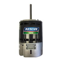
The RESCUE® EZ13 ECM Blower Motor is a high-efficiency, variable-speed replacement motor designed for Electronic Commutated Motor (ECM) applications in HVAC systems. It allows homeowners to benefit from variable speed motor technology, offering improved efficiency and performance.
Function Description:
The RESCUE® EZ13 motor is designed to replace existing ECM blower motors in air handling units and furnaces. It operates as a direct-drive centrifugal blower, moving air through the HVAC system. A key feature is its auto rotation sensing technology, which allows the motor to determine the proper direction of rotation for the specific application without requiring manual programming. When first powered on and receiving a run signal, the motor performs a rotation sensing process, running for approximately 20 seconds in each direction. Once the correct operating direction is determined, this information is stored, and the process is not required for subsequent run signals unless system power is lost for more than 60 seconds. If the motor cannot sense the proper rotation, it defaults to counter-clockwise rotation. The motor is designed for continuous, air-over duty, meaning it must be mounted within the air stream of an air moving device like a fan to prevent overheating and damage.
Important Technical Specifications:
- Horsepower: Available in 1 HP, 3/4 HP, and 1/2-1/3 HP configurations.
- Voltage: Single-phase (1Ø), 115/208-230 Vac. The motor ships connected for 208-230 Vac systems, but can be configured for 115 Vac operation using an accessory plug.
- Speed: 1050 RPM.
- Hertz: 60 or 50 Hz.
- Frame: NEMA® 48.
- Mounting: Belly-band.
- Operating Temperature: Should not exceed 104°F (40°C) or be less than -20°F (-29°C).
- Voltage Tolerance: Voltage to the motor control unit must be within plus or minus 10% of the nameplate voltage to avoid overheating or loss of performance.
Usage Features:
- Dual Voltage: Supports both 115 Vac and 208-230 Vac systems, making it versatile for various installations.
- Multi-speed Operations: Features five 24-volt taps for multi-speed control, allowing for customized airflow settings.
- Auto Rotation Sensing Technology: Eliminates the need for manual programming of rotation direction, simplifying installation.
- Ready to Install: Designed for straightforward installation, with no complex programming required.
- Installation Process:
- Safety First: Always turn off electrical power at the fuse box or circuit breaker panel and wait four minutes for capacitors to discharge before handling electrical connections.
- Blower Housing Removal: Disconnect the furnace wiring harness from the old motor and remove the blower housing from the HVAC equipment.
- Connector Verification: Connect the furnace wiring harness to the new RESCUE® EZ13 motor to ensure proper fit, then disconnect and set aside.
- Original Motor Removal: Loosen the set screw on the old motor shaft, remove the screw securing the belly-band mounting bracket, and remove the old motor. Verify the new motor matches the horsepower and voltage rating of the original.
- Replacement Motor Installation (Belly-Band): Ensure the motor's voltage setting matches the system (change to 115 Vac if needed using the accessory plug). Insert the motor into the mounting bracket, ensuring the belly-band is positioned at the midpoint between the vents, not on the end bell (control) housing. The Drip Slot on the motor should be at or near the 6 o'clock position to allow condensation drainage. Secure the bracket to the motor by tightening the mounting screw, ensuring it is securely fastened to minimize noise and vibration.
- Replacement Motor Installation (Air Handling Unit): Insert the motor shaft into the blower wheel, securing the motor to the blower housing. Align the blower wheel, centering it in the housing and aligning its set screw to the flat of the motor shaft. Secure the blower wheel to the motor shaft by tightening the set screw to a torque setting of 157 in-lbs.
- Blower Assembly Reinstallation: Follow the manufacturer's instructions to reinstall the blower assembly in the HVAC system. Connect the furnace wiring harness to the replacement motor.
- Start-Up and Operation: Upon initial power-up and run signal, the motor performs a rotation sensing process (approx. 20 seconds in each direction). This information is stored for future operations. If power is lost for over 60 seconds, the sensing process re-initiates.
- Operating Mode Checklist: Includes checks for start-up/shut-off delays (normal delays of 10-12 seconds before starting and 30-255 seconds before reaching full speed/turning off), unusual noise or vibration, motor amperage (within 10% of nameplate at highest speed), and correct airflow in all operating modes.
Maintenance Features:
- Safety Precautions: Always disconnect electrical power and allow the motor to stop and capacitors to discharge (wait four minutes) before performing any maintenance.
- Periodic Inspection: Regularly inspect the installation for dirt accumulation, unusual noises or vibration, overheating, worn or loose couplings, high motor amps, poor wiring, overheated connections, loose mounting bolts or guards, and worn motor starter contacts. Check wiring harnesses and control connectors for shorts, detached wiring, or loose connections.
- Cleaning: Remove dirt accumulation, especially around vent openings, by vacuuming. Dirt accumulation can cause motor overheating and is a fire hazard.
- Solvent Warning: Do not use solvents, as they may damage motor insulation, finish, or bearing lubricants and are highly flammable.
- Lubrication: Ball bearing motors are permanently lubricated and require no maintenance.
- Troubleshooting: A dedicated section provides guidance for common issues:
- Motor not spinning or running abnormally: Verify thermostat call for activity, check circuit breaker, ensure secure wiring harness connections, inspect for shorts or detached wiring, and check the control for damage.
- Motor rattles or makes excessive noise: Inspect motor and blower for accumulated dirt or internal debris, check blower fan for bent/missing blades or misaligned/unsecured mounting, inspect blower housing for cracks/dents/corrosion, ensure secure mounting of blower housing to chassis, and verify the motor shaft spins freely.
- Warranty: Nidec Motor Corporation (NMC) extends a limited warranty to the purchaser for 24 months from the date of original purchase or 30 months from the date of manufacture, covering defects in materials and workmanship under normal use. The warranty does not cover losses or damages due to misuse, accident, abuse, neglect, negligence, unauthorized modification, use beyond rated capacity, or improper installation, maintenance, application, or use. Purchasers must notify NMC or the dealer within 30 days of discovering any warranty defects.