8
4. Secure the bracket to the motor by tightening the bracket mounting screw.
The motor must be securely fastened to minimize noise and prevent vibration. Ensure the bell-band
legs cannot be moved. For secure mounting, use high-quality bolts of the largest possible diameter.
Step 6: Install the Replacement Motor in the Air Handling Unit
1. Insert the motor shaft into the blower wheel, securing the motor to the blower housing.
2. Align the blower wheel so it is properly centered in the blower housing, aligning the wheel’s set screw to
the flat of the motor shaft.
3. Secure the blower wheel to the motor shaft by tightening the set screw to a torque setting of 157 in-lbs.
Step 7: Reinstall the Blower Assembly in the HVAC System
1. Follow the manufacturer’s installation manual for blower installation instructions.
2. Connect the furnace wiring harness to the replacement motor.
Motor Start-Up and Operation
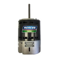
The first time the RESCUE
®
EZ13 motor is powered on and receives a run signal from the system control
board, it performs a rotation sensing process. The motor runs for approximately 20 seconds in each direction
to determine the proper direction for the application. Once the motor determines the proper operating direction,
the information is stored and the motor does not require the process for subsequent run signals. In the event of
system power loss exceeding 60 seconds, the rotation sensing process is re-initiated at the next run signal
after power is restored. If the motor is unable to sense the proper rotation, the motor uses default rotation,
which is counter-clockwise.