EasyManua.ls Logo

Nidek Medical LE-9000LX - User Manual

Nidek Medical LE-9000LX
145 pages
Print Icon
To Next Page IconTo Next Page
Loading...
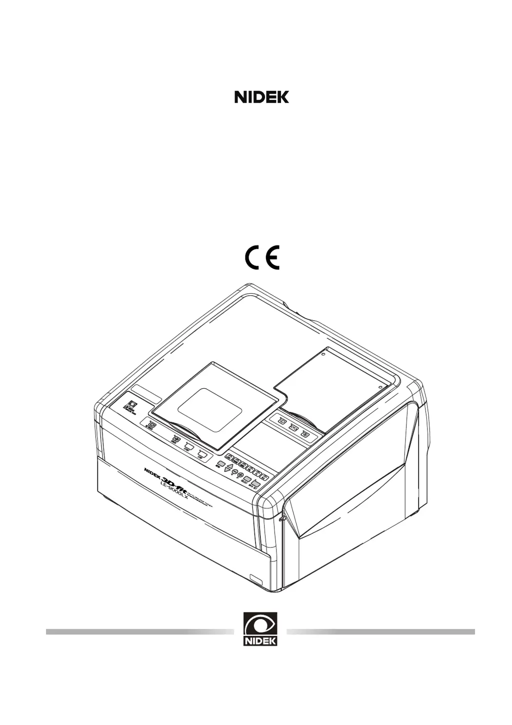
PATTERNLESS EDGER
Model LE-9000LX
OPERATOR’S MANUAL

Table of Contents

Questions and Answers

  • E
    Emily PerezAug 4, 2025
    What to do if processing does not start on my Nidek Medical Edger?
    • J
      Jessica RogersAug 4, 2025
      If processing doesn't start when you press the start button and a beep sounds, it could be because the soundproof cover is open. Please close the cover. Alternatively, the instrument may be trying to process the same side of the lens. Press the start button to change the indication from R or L to process the opposite lens.
  • P
    Phillip SmithAug 9, 2025
    Why does retracing start automatically on my Nidek Medical LE-9000LX Edger?
    • J
      jillellisAug 9, 2025
      Automatic retracing, indicated by blinking LEDs, occurs when there's a significant difference (1 mm or more) in circumference between the right and left rims. To resolve this, trace only one rim and then proceed to edge the lens.
  • B
    Brandon TaylorAug 14, 2025
    What to do if the Nidek Medical LE-9000LX Edger displays "Use chuck for half-eye lens"?
    • B
      Bobby PalmerAug 14, 2025
      If the message "Use chuck for half-eye lens" appears and the instrument stops, use the adapter set designed for half-eye lenses.
  • J
    Joseph RussellAug 19, 2025
    What to do if the stylus comes off the groove of frame during tracing with Nidek Medical LE-9000LX Edger?
    • D
      Dawn GrossAug 19, 2025
      If the stylus comes off the groove during tracing and the LED blinks, press the button to return the stylus to its original position and try tracing again. For frames that are sharply warped, trace only one rim while holding the other rim in place.
  • R
    Robert GravesAug 25, 2025
    Why does the Nidek Medical Edger change to Bevel simulation display during lens shape measurement?
    • C
      Crystal BartonAug 25, 2025
      The display changes to the Bevel simulation and part of the outline blinks because the lens size is insufficient for the selected outline. Press the stop button, then either use a larger lens or change the lens layout.
  • M
    michelle47Aug 29, 2025
    How to fix Nidek Medical LE-9000LX memory function if it cannot be used?
    • D
      Darrell HodgeAug 29, 2025
      To enable the memory function, set the parameter "10) Ext. interface" to "None".

Summary

§1 INTRODUCTION

1.1 Outline of the Product

Describes the fully-automatic lens edger and its functions.

1.2 Symbol Information

Explains symbols used for safety, operation, and identification in the manual.

§2 SAFETY

2.1 Cautions in Use

Crucial warnings and precautions for safe operation of the instrument.

2.2 Storage

Specifies conditions for storing the instrument to prevent damage or malfunction.

2.3 Transport

Details precautions and methods for safely moving the instrument.

2.4 Installation

Outlines required environmental conditions and placement for instrument installation.

2.5 Wiring

Instructions and cautions for electrical connections to ensure safe operation.

2.6 After Use

Procedures for proper shutdown and cleaning after daily use.

2.7 Maintenance and Check

Recommendations for periodic inspections and checks for instrument longevity.

2.8 Disposal

Guidance on proper disposal of the instrument and its components according to regulations.

2.9 Labels

Illustrates and explains various safety labels found on different parts of the instrument.

2.10 Safety Function

Details safety features like soundproof cover check and stop key functions.

§3 CONFIGURATION

3.1 Whole system

Overview of the instrument's main components and their arrangement.

3.2 Rear Side of Main Body

Identifies ports and controls located on the rear of the instrument.

§4 OPERATING PROCEDURES

4.1 Operation Flow

Provides a step-by-step flowchart of the entire lens processing operation.

4.2 Preparation

Steps required to prepare the instrument before starting operations.

4.3 Tracings

Explains the process of tracing frame shapes for accurate processing.

4.4 Layouts

Information on setting up lens layouts and processing conditions.

4.5 Blocking Lenses

Procedures for blocking lenses, which positions them for processing.

4.6 Processings

Details various processing methods available for lenses.

4.7 Checking the Lens Size

Procedures for verifying and adjusting the lens size after processing.

4.8 Processing the Opposite Lens

Instructions for processing the second lens of a pair.

4.9 Removing the Lens Cup

Procedure for safely removing the lens cup.

4.10 Treatment after Daily Use

Daily cleaning and shutdown procedures for the instrument.

4.11 Daily Checks

Daily checks to ensure proper operation before and after use.

4.12 Periodical Check

Recommended schedule for periodic inspections and maintenance.

§5 OTHER FUNCTIONS

5.1 Process Counter

Displays counts of lenses processed by material.

5.2 Parameter Settings

Guides users on how to configure various operational parameters.

5.3 Storing Initial Display

Allows saving custom display settings for startup.

5.4 Storing and Calling Up the Traced Data

Functionality for saving and retrieving lens tracing data.

§6 TROUBLESHOOTING GUIDE

§7 STORAGE

§8 MAINTENANCE

8.1 Wheel Dressing

Process for maintaining the grinding wheels for optimal performance.

8.2 Replacing the Water and Filter (115 V regions)

Steps for replacing water and filter, with and without FP-100.

8.3 Replacing the Water and Filter (230 V regions)

Steps for replacing water and filter for 230V units.

8.4 Replacing Fuses

Instructions for replacing blown fuses.

8.5 Cleaning the Exterior

How to clean the instrument's outer surfaces.

8.6 Size Adjustment

Adjusting lens size compensation for proper fit.

8.7 Adjusting Bevel Position

Correcting bevel position if it deviates from the designated spot.

8.8 Adjusting Axis Shift

Adjusting the lens axis angle for precise processing.

8.9 Adjusting Lens Margin Allowed for Finishing

Compensating lens margin for finishing.

8.10 PD Adjustment

Adjusting the PD value if it doesn't match the finished lens.

8.11 Adjustment for Polishing

Adjustments related to polishing, especially for unpolished edges.

8.12 Tracer Calibration

Calibrating the tracing unit for accurate measurements.

8.13 List of Consumable Articles

Lists parts and accessories that are consumed during operation.

§9 SPECIFICATIONS

§10 ACCESSORIES

10.1 NIDEK-type Accessories

Detailed list of accessories provided by NIDEK.

10.2 WECO-type Accessories

Detailed list of accessories compatible with WECO-type systems.

10.3 SANTI-type Accessories

Detailed list of accessories compatible with SANTI-type systems.

APPENDIX A SUPPLEMENT

A.1 Selection of Tracing

Guidance on choosing the appropriate tracing method.

A.2 Selection of Layout

Overview of different layout forms for inputting lens data.

A.3 Selection of Blocking

Guide to selecting the correct blocking mode for lenses.

A.4 Selection of Processing

Guide to selecting the appropriate processing mode.

APPENDIX B ERROR CODE

Nidek Medical LE-9000LX Specifications

General IconGeneral
BrandNidek Medical
ModelLE-9000LX
CategoryEdger
LanguageEnglish

Related product manuals