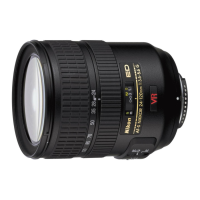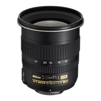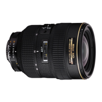
Do you have a question about the Nikon AF-S Zoom-Nikkor ED 24-70mm/F2.8G (IF) and is the answer not in the manual?
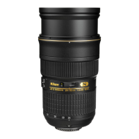
| Focal Length | 24-70mm |
|---|---|
| Maximum Aperture | f/2.8 |
| Minimum Aperture | f/22 |
| Lens Mount | Nikon F |
| Angle of View | 84° - 34°20' |
| Lens Construction | 15 elements in 11 groups |
| Nano Crystal Coat | Yes |
| Super Integrated Coating | Yes |
| Autofocus | Yes |
| AF-S (Silent Wave Motor) | Yes |
| Internal Focusing | Yes |
| Diaphragm Blades | 9 (rounded) |
| Filter Size | 77mm |
| Lens Hood | HB-40 |
| Lens Case | CL-M3 |
| Image Stabilization | No |
| Format Compatibility | FX/35mm |
| Special Elements | 3 ED glass elements |
| Minimum Focus Distance | 0.38m |
| Dimensions (Diameter x Length) | 83 x 133mm (3.3 x 5.2 in) |
| Weight | 900g |
General precautions and preparation steps before servicing the lens.
Remove the filter ring and its associated screws.
Take out screws and remove the 1st lens-G unit.
Remove the sheet, rubber ring, and tape from lens parts.
Disassemble the 5th lens group, zoom brush, and M/A brush.
Remove the bayonet mount unit and lens groups (4th, 3rd).
Remove various tubes, rings, and electronic units from the lens.
Detach the MF ring and remove the GMR unit.
Remove the main PCB unit and SWM units.
Remove focus components, brushes, washers, hood ring, and lead rings.
Remove the hood fixed ring and the 1st lens-G lead ring.
Remove the SWM brushes from the lens.
Attach SWM relay-FPC, brushes, and assemble lens lead key ring.
Mount hood fixed ring, SWM unit, install washers, and focus fixed tube.
Install Main PCB, GMR unit, MF ring, and Zoom FPC.
Assemble exterior tubes, zoom ring, lens groups, and bayonet mount.
Perform adjustments for limit plate, aperture lever, brushes, and filter ring.
Set up the computer, software, and necessary devices for inspection.
Adjust electrical device and inspect lens operations including GMR encoder.
Inspect lens driving stop accuracy and driving time using software.
Manage FLASH-ROM data and note adjustments needed after part replacement.
Prepare test charts and set up camera for aberration measurement.
Write compensation data and verify focus using software.
