EasyManua.ls Logo

Nikon AF-S VR Zoom-Nikkor ED 24-120mm f/3.5-5.6G IF User Manual

Nikon AF-S VR Zoom-Nikkor ED 24-120mm f/3.5-5.6G IF
101 pages
To Next Page IconTo Next Page
Page #1 background imageLoading...
Page #1 background image
JAA78271-R.3598.A
作成承認印
配布許可印
REPAIR MANUAL
NIKON CORPORATION
Tokyo, Japan
Recycled paper
Printed in Japan May 2003
Copyright 2003 by Nikon Corporation.
All Rights Reserved.
AF-S VR Zoom-Nikkor
ED 24-120mm f/3.5-5.6G IF
INC
Question and Answer IconNeed help?

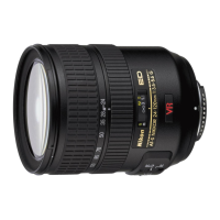
Do you have a question about the Nikon AF-S VR Zoom-Nikkor ED 24-120mm f/3.5-5.6G IF and is the answer not in the manual?

Nikon AF-S VR Zoom-Nikkor ED 24-120mm f/3.5-5.6G IF Specifications

General IconGeneral
Focal Length24-120mm
Maximum Aperturef/3.5-5.6
Lens Construction15 elements in 13 groups
Filter Size72mm
Lens MountNikon F
Diaphragm Blades7
Format CompatibilityFX/35mm
Weight575g (20.3 oz)
Image StabilizationYes
AutofocusYes
Minimum Focus Distance0.5m (1.64 ft)
Dimensions77.5 x 94.5 mm

Summary

REPAIR MANUAL

AF-S VR Zoom-Nikkor ED 24-120mm f/3.5-5.6G IF

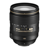
Main product model and specifications for repair.

SPECIFICATIONS

Pre-Disassembly Precautions

DISASSEMBLY PROCEDURES

Component Disassembly

PCB and VR Unit Disassembly

Base Plate and Zoom Ring Disassembly

Scale Ring and Zoom Ring Procedures

SWM Unit and 4th Lens Group Frame

Cam Ring and 3rd Lens Group

2nd Lens Group and Sliding Ring

Aperture Blade Housing and VR Unit

ASSEMBLY PROCEDURES

Aperture Housing and VR Unit Assembly

Assembly of aperture housing and VR unit.

2nd Lens Group and Rings Assembly

Cam Ring and 3rd Lens Group Assembly

4th Lens Group Frame and SWM Unit Assembly

MR ENCODER OUTPUT WAVEFORM INSPECTION/ADJUSTMENT

BASE PLATE AND PCB ASSEMBLY

INDEX RING, FOCUS RING AND BAYONET

FOCUS RING OPERATIONS INSPECTION & ADJUSTMENT

APERTURE LEVER POSITION ADJUSTMENT

Lens Alignment Procedures

Alignment Equipment Setup

Setting up the lens alignment equipment.

4th Lens Group Temporary Alignment

4th Lens Alignment Chart Shooting

4th Lens Group Alignment Process

Line Generator and Camera Alignment Steps

Adjusting X- and Y-lines with the line generator.

Positioning Tool Creation Guide

Setting Board Creation Guide

FOCUS MOVEMENT ADJUSTMENTS

Back-Focus Adjustment Procedure

Adjusting back-focus using washer thickness.

MAIN PCB INSPECTION & ADJUSTMENT PREPARATION

MR DUTY ADJUSTMENT PROCEDURE

MR Duty Adjustment Steps

Steps to adjust MR duty using software and oscilloscope.

DRIVING FREQUENCY & MOTOR CONTROL ADJUSTMENT

Automatic Adjustment Process for Motor Control

Performing automatic adjustment for frequency/motor control.

Manual Adjustment Process for Motor Control

Steps for manual adjustment if automatic fails.

Manual Motor Control Adjustment Details

INSPECTION OF LENS OPERATIONS

PC-Based Inspection Overview

Inspecting lens operations via PC.

AF-S Zoom Lens Inspection Program Menu

MR Encoder Operations Inspection

Lens-Servo Stop Accuracy Inspection

Lens-Servo Time Inspection

Switches and Lens Conditions Inspection

Switch and Condition Check Steps

Verifying switch operations and lens status.

Main PCB Inspection & Adjustment Preparation

Required Adjustments for PCB/SWM/MR

Key adjustments for main PCB, SWM, or MR encoder.

Adjustment for Electrical Device

EEPROM Fixed Values Writing Procedure

Process for writing fixed values to EEPROM.

MR Duty Adjustment Procedure

Steps to adjust MR duty via software.

Drive Frequency/Motor Control Automatic Adjustment

Automatic Adjustment Steps

Performing automatic adjustment for frequency/motor control.

Manual Adjustment for Motor Control

Low-speed Adjustment Steps

Conducting low-speed adjustment.

High-speed Adjustment Steps

Conducting high-speed adjustment.

MR Encoder Operation Inspection

Operation Check and Result Interpretation

Verifying MR encoder operation results.

Lens Driving Stop Accuracy Inspection

Inspection Screen and Accuracy Check

Inspecting how accurately the lens stops driving.

Lens Driving Time Inspection

Inspection Screen and Time Measurement

Measuring the time taken for lens driving.

Final Lens Operations Inspection

Post-Inspection Actions and Troubleshooting

Actions to take after inspection based on results.

VR ADJUSTMENT PROCEDURES

VR Adjustment Equipment Setup

Setting up the VR lens adjustment equipment.

VR Mode Switch Inspection

Inspection Window and Execution Steps

Checking the VR mode switch status.

VR LENS POSITION ADJUSTMENT

VCM Polarity Adjustment Procedure

Adjusting VCM polarity and writing compensation.

VR Unit Calibration Adjustments

VR GYRO ADJUSTMENT PROCESS

Laser Switch and Telephoto Setting for Gyro

Adjusting the laser switch for gyro calibration.

VR Performance Adjustments

VR PERFORMANCE JUDGMENT STANDARD

VR Unit Control Check

Initial check of VR unit control and causes of failure.

Vibration Reduction Rate Check

Assessing VR performance based on vibration reduction.

ABERRATION COMPENSATION DATA WRITING

Preparation for Data Writing Process

Preparing tools and software for aberration compensation.

Test Chart Creation Guide

Guide to creating the test chart.

Writing Aberration Compensation Data

Camera and Software Configuration Steps

Configuring camera and software for data writing.

Self-Made Tool Construction Steps

WIRING DIAGRAM FOR LENS COMPONENTS

Related product manuals