Chapter 3 Names of Parts and Their Functions
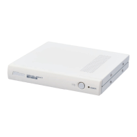
1 DS-U3 DS Camera Control Unit
- 6 -
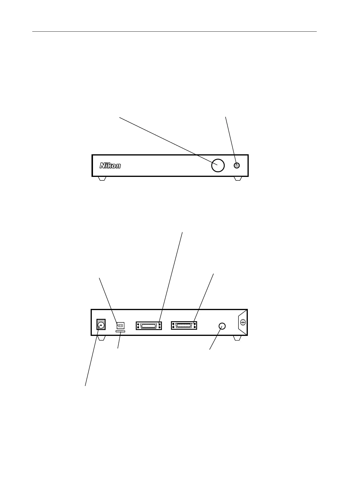
(2) Front of the DS-U3
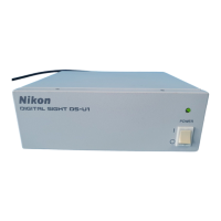
(3) Rear of the DS-U3
DC IN 12V IEEE1394 CAMERA1 CAMERA2 EXT.I/O
Power switch
This is a push switch. Press to
turn it on. Press again to release
and turn it off. When the power is
on, the power indicator lights up.
Power indicato
When power is turned on, the indicator
first flashes green, and then turns to
green. When the indicator lights up in
green, the DS-U3 is ready for operation.
IEEE1394 connecto
Connects to a PC via an IEEE
1394b cable.
C
MERA 1 connecto
Connects to the DS camera head.
* Be sure to turn off power before
connecting or disconnecting the
connector: otherwise, the equipment
malfunctions.
DC lN 12V connecto
Use the supplied AC adapter.
C
MERA 2 connecto
Connects to the DS camera head.
* Be sure to turn off power before
connecting or disconnecting the
connector: otherwise, the equipment
malfunctions.
E
T. l/O connecto
When the DS-Qi1Mc is connected,
image capture can be externally
triggered by supplying external trigger
signals from this port.
(Cannot be used unless DS-Qi1Mc is
connected.)
Holde
Keeps the cable from being
pulled off the lEEE1394
connector.