Chapter 4 Connecting and Installing the Equipment
3 Connection Methods
- 13 -
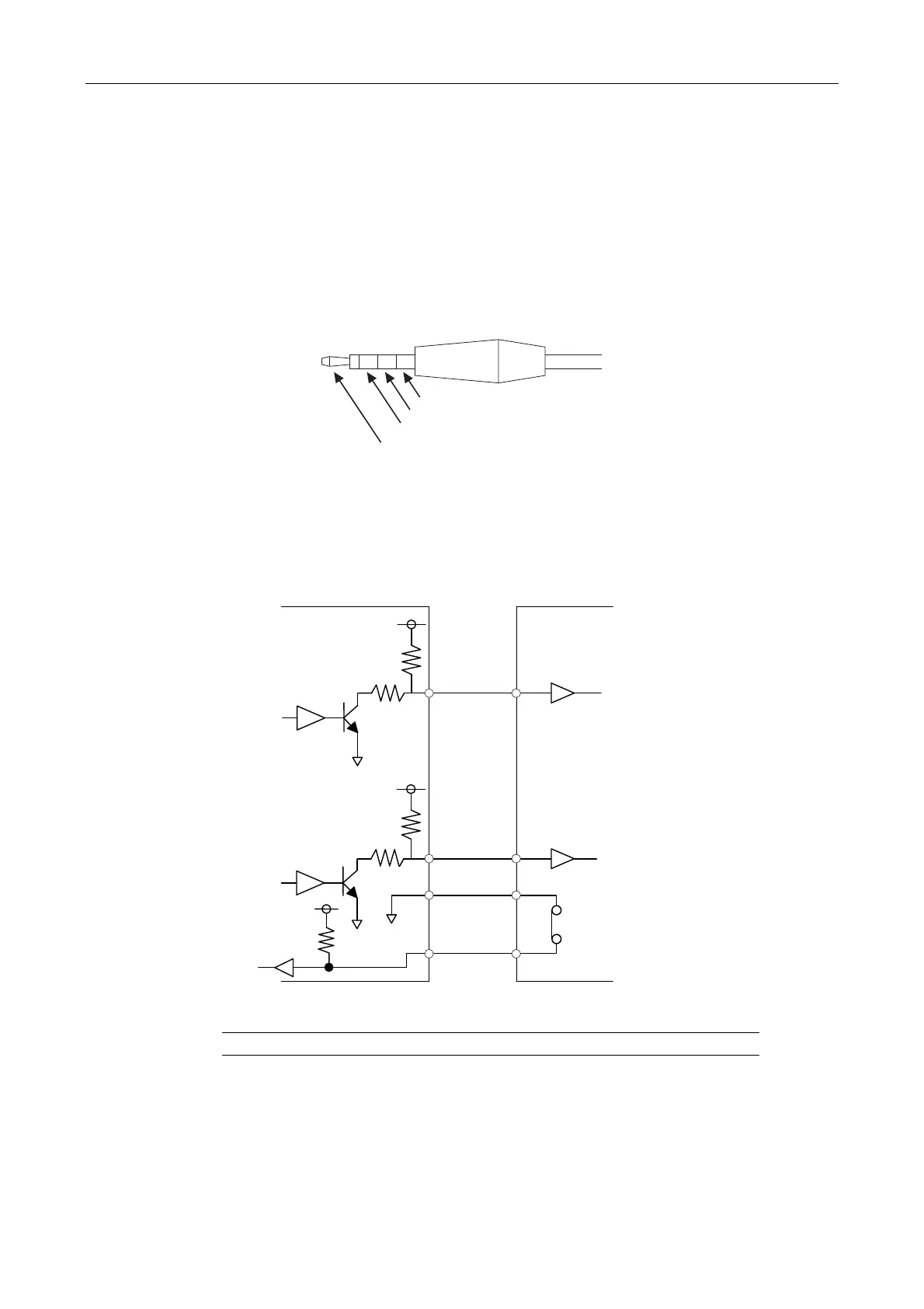
(3) When connecting external devices (trigger signal output devices)
Before making a connection, always turn off the DS-U3 and external devices.
When the DS-Qi1Mc is connected, image capture can be triggered from an external device by
supplying trigger signals to the EXT. I/O connector.
If you are connecting your own external device, use a device that meets the following
specifications.
Connector: φ3.5 mm, 3-pole pin jack
Functions
Pin 1: Exposure timing signal (output: HI active)
Pin 2: Trigger enable signal (output: HI active)
Pin 3: External trigger signal (input: HI active)
* The TTL or LVTTL level signal can also be input from Pin 3.
GND
Pin 2
Pin 1
Pin 3
3.3 V
4.7 kΩ
100 Ω
3.3 V
10 kΩ
Pin 1
Pin 2
Pin 3
DS-U3 External device
Operates when the switch is off
(open)
Pulse width: 1 ms or more
3.3 V
4.7 kΩ
100 Ω
 Loading...