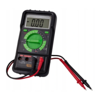
42
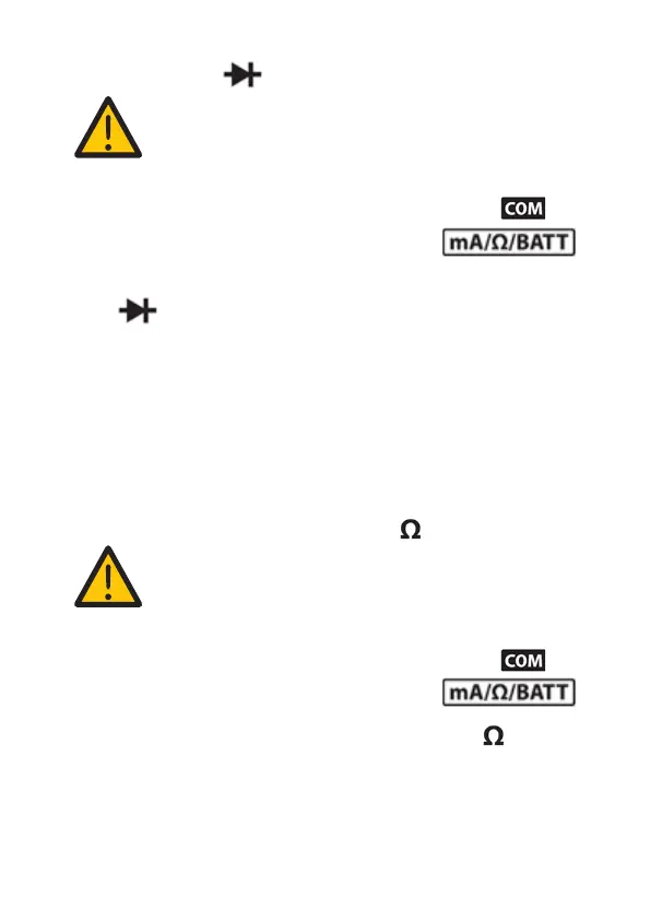
7.9 Diode test ( )
NOTICE! Risk of damage!
Make sure that all circuit parts, circuits and
components, as well as all other measuring
objects are completely dead and discharged.
1. Connect the black measuring probe to the (5)
socket, connect the red one to the
input socket (6).
2. Use the measurement dial (2) to select the symbol
.
3. Connect the red wire p to the tested diode anode,
connect the black wire p to the tested diode
cathode.
4. The mulmeter will show the diode approximate
forward voltage. If the wires are reversed, “1” will be
shown. Reverse the polarity to determine whether
the diode is faulty or not.
7.10 Resistance measurement ( )
NOTICE! Risk of damage!
Make sure that all circuit parts, circuits and
components, as well as all other measuring
objects are completely dead and discharged.
1. Connect the black measuring probe to the (5)
socket, connect the red one to the
input socket (6).
2. Use the measurement dial (2) to select ( ). If you
do not know the measurement range, rst select the
highest possible range, then switch to lower ones.
3. Connect the measuring ps to the measured part.