18
nixiediy@gmail.com
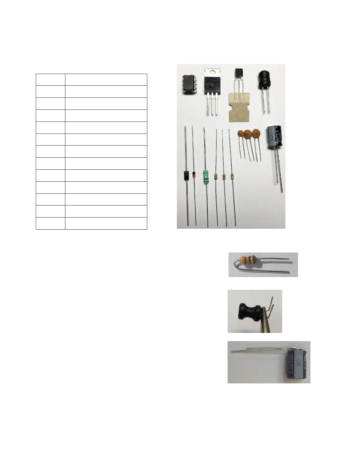
3. High voltage generator components preparation for insertion into the board and
soldering order
U2 MC34063
Q1 BC557
Q2 IRF840
D3 UF4004
D2 1N914
L1 Inductor 330uH
C1 2.2uF, 250V
C3, C5 0.1uF
C4 2.2nF
R4 0.5Ω 0.5W
R1 1k
R3 3.6k
R2 470k
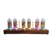
3.1. All resistors (except R4) leads bend in accordance with this picture that each
resistor place on board surface will be minimal.
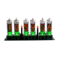
3.2. By using long nose pliers, bend inductor L1 leads. Bending the
leads directly near casing may discontinue this inductor coil wires
that are soldered to leads.
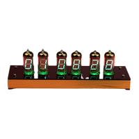
3.3. Bend the capacitor C1 leads.