EasyManua.ls Logo

Nixie Clock IN-16 User Manual

Default Icon
20 pages
To Next Page IconTo Next Page
Page #1 background imageLoading...
Page #1 background image
Warm Tube Clock
Assembly Instructions for the „IN-16 Nixie shield“
Document Version: 2011-01-05
www.elektronika.ba
-1-
Warm Tube Clock
Assembly Instructions for the “IN-16 Nixie shield
Introduction
Congratulations on your purchase of OSH Nixie Tube Clock. In this document you will see all steps
you need to follow in order to successfully assemble the “IN-16 Nixie shieldof this device.
Before we start, please make sure that you have all required parts that come for the “IN-16 Nixie
shield:
Qty
Value
Device
Parts
2
2x6 MALE PIN HEADER
PINHD-2X6
PIN_MAL_1, PIN_MAL_2
1
3k9
R-EU_0204/2V
R3
1
10k
R-EU_0204/2V
R4
1
10nF
C-EU025-024X044
C3
1
47uF/16V
CPOL-EU-HORI
C1
1
100nF-1uF
C-EUC0805
C2
2
910k
R-EU_0207/10
R1, R2
4
IN-16 NIXIE TUBE
IN-16-X-NEW-NODOT
NIX1, NIX2, NIX3, NIX4
4
LED 1210 COMM ANODE
LED-TRICOLOR
LED1, LED2, LED3, LED4
2
NIXIE-DOT
NIXIE-DOT
NIX-LDOT, NIX-UDOT
1
TLC59401
TLC59401
IC1
4
TLP627 SMD
TLP627V1
OPT1, OPT2, OPT3, OPT4
List of all parts for the “IN-16 Nixie shield board
All parts should be assembled in correct order, starting from SMD components to low profile
components and finally to high profile ones. Component locations are not marked on PCB because a
“clean look” of the shield is very important. So, component (Part) locations are in the following image
and their values are in the above table.
Note: The assembly of this shield PCB implies that you have already successfully assembled the
“main board” of the Warm Tube Clock.
Question and Answer IconNeed help?

Do you have a question about the Nixie Clock IN-16 and is the answer not in the manual?

Nixie Clock IN-16 Specifications

General IconGeneral
BrandNixie Clock
ModelIN-16
CategoryClock
LanguageEnglish

Summary

Introduction to Warm Tube Clock

Step 1: Solder TLC59401 SMD IC

Prepare and Apply Solder Paste

Prepare PCB pad, apply liquid solder paste for IC placement.

Place and Hot-Plate Component

Place IC with tweezers, use clothing iron for 'hot-plating'.

Hot-Plate Soldering Process

Pre-heat PCB, melt solder paste, inspect for proper soldering.

Step 2: Solder RGB LEDs

Solder RGB LEDs

Place and solder RGB LEDs, noting common anode and orientation.

Finished LED Soldering

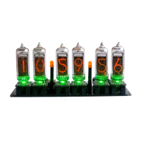
View of correctly soldered RGB LEDs on the PCB.

Step 3: Solder C3 Capacitor

Solder C3 Capacitor

Place and solder the 10nF (103) C3 capacitor for voltage filtering.

Step 4: Solder Resistors R3 and R4

Solder 3k9 and 10k Resistors

Solder 3k9 (R3) and 10k (R4) resistors for LED current and pull-up.

Step 5: Solder Pin Headers

Connect Main and Shield Boards

Insert and solder 2x6 male pin headers connecting main and shield boards.

Step 6: Test TLC59401 Operation

Initial Test and High Voltage Warning

Connect power, observe LED blinking, heed high voltage warning.

Troubleshooting Assembly Issues

Steps for re-soldering TLC59401 and firmware checks.

Step 7: Solder Opto-couplers

Solder TLP627 SMD Opto-couplers

Place and solder TLP627 SMD opto-couplers (OPT1-OPT4).

Complete Opto-coupler Soldering

Solder all remaining pins of the opto-couplers to complete the step.

Step 8: Solder 910k Resistors

Solder 910k Resistors for Nixie Dots

Solder 910k resistors (R1, R2) for Nixie dots and NPN transistors.

Step 9: Solder Electrolytic Capacitor C1

Solder 47uF Electrolytic Capacitor

Bend and solder the 47uF electrolytic capacitor (C1) for power storage.

Step 10: Solder SMD Capacitor C2

Solder 100nF-1uF SMD Capacitor

Solder 100nF-1uF SMD capacitor (C2) for supply voltage filtering.

Step 11: Solder Nixie Dots

Prepare and Solder Nixie Dots

Solder Nixie dots, adjust height, and test with power supply.

High Voltage Warning for Nixie Dots

Caution regarding high voltage (200V DC) during testing.

Solder Nixie Tubes

Solder the upper Nixie dots and prepare for Nixie tube installation.

Step 12: Solder IN-16 Nixie Tubes

Prepare Nixie Tubes for Soldering

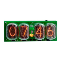
Drill plastic bottom, cut unused Nixie dot leads, place tubes.

Solder Nixie Tubes Correctly

Solder anode pin first, then other pins, ensuring tubes are straight.

Assembly Complete

Congratulations on completing the assembly of the IN-16 Nixie shield.

Tests

Related product manuals