21
nixiediy@gmail.com
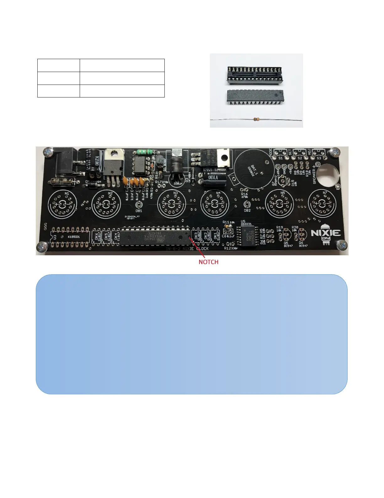
5. Microcontroller circuit components assembly
U4 Atmega328P-PU
R11 10kΩ
U4 Socket 28 pin socket
5.1. Take the resistor R11 and bend it, like pointed in item 3.1. Insert resistor into the board holes
marked as R11 and solder it leads.
NOTES:
• Do not place the microcontroller U4 into the socket before you mount the socket onto
the board.
• Mount the socket such that the notch in the socket lines up with the notch marking in
rectangular outline printed on the board.
• After inserting a socket into the board, solder its two opposite-corners pins first. This will
hold the socket in place. Look at it carefully to check it proper orientation. If not, it is easy
to heat one or both pins and adjust the socket. Only if everythis correct, solder the rest
pins. Remember: to keep the soldering time per pin brief. The pins do not need to clip.
• The microcontroller notch indicates how IC should be mounted into the socket after the
socket has been soldered into the PCB.