27
nixiediy@gmail.com
10.5. Disconnect power supply.
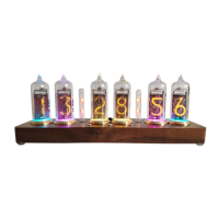
11. Neon dot circuit components
DB1, DB2 Neon Bulb
R16, R17 270kΩ
R15 10kΩ
Q7 MPSA42
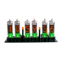
11.1. Resistors R15, R16 and R17 leads bend in accordance with item 3.1. Insert them into locations
R15, R16, R17 and solder their leads as pointed on the picture
.
11.2. Install the transistor Q7 legs into the board holes marked as Q7 that its case flat edge is above
the flat edge of the placement marking. Solder it each leg in accordance with sub-item 10.2
directions.
NOTE: Neon bulbs DB1 and DB2 you must install later after nixie tubes soldering.