- 7 - Gyropilot_2_um_EN_7_30
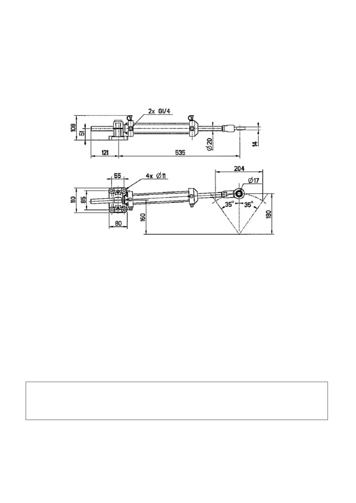
2.2.2 Hydraulic linear drive type 40 for outboard mounting
You will find with the hydraulic linear drive, the manufacturer mounting instructions.
Dimensions for installation hydraulic linear drive type 40 outboard
2.2.3 Installation procedure
- Put the rudder to the axis
- Unscrew half the way the tip at the end of the drive rod, and pull the rod half the way out
such as the length between the axis of the linear support and the thrust axis is equal to
the rod length
- Place the linear drive at 90° of the rudder arm
- Fixed it with 4 stainless steel screws and nuts.
- Grease the thrust axis of the linear drive and fix it on the rudder arm or rudder sector
with the supplied nylstop nut.
- Adjust the rod tip on the same axis than the thrust axis and block it in position with the
counter-nut.
- Insert the thrust axis in the rod tip and block it with a lynch pin.
WARNING:
Check that the mechanical rudder stops are in use. If the l
inear drive is used as a rudder
stop, it could be irremediably damaged.
 Loading...