- 6 - Gyropilot_2_um_EN_7_30
2.2 Installation of the hydraulic linear drive
2.2.1 Linear drive for inboard mounting
You will find with the hydraulic linear drive, the manufacturer mounting instructions.
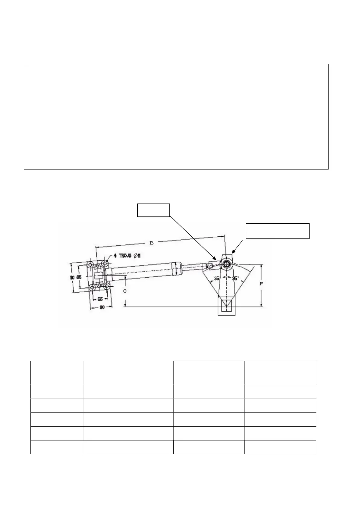
Dimensions for installation
Pack type
B
the rod half the way out
F G
60 727mm 240mm 218mm
40 627mm 190mm 172,5mm
32 533mm 170mm 160mm
27 472mm 150mm 136,5mm
Mini 395mm 129mm 117mm
WARNING:
The force developed by a hydrauli
c linear drive is very strong and could result in serious
damage if impropally installed.
The linear drive and the hydraulic pump must be positioned on an horizontal plan.
Make sure that the linear drive support is positioned in the way that the
sector is in the same horizontal plan as the linear drive axis.
The mounting
of the linear must be very rigid and you should not hesitate to strengthen it with
a stainless steel plate strongly attached to the boat.
The rod of the cylinder is very fragile, and must not receive shocks, which could cause the rip
of the lip seal and therefore an oil leak.
Rudder arm
Rod tip
 Loading...