- 9 - Gyropilot_2_um_EN_7_30
2.4.2 Installation procedure
1. Present the threaded rod in front of the rudder shaft, measure the maximum distance
where you can place the sensor, in function of the rod length. The sensor arm will have
to be able to rotate by 70° in both ways.
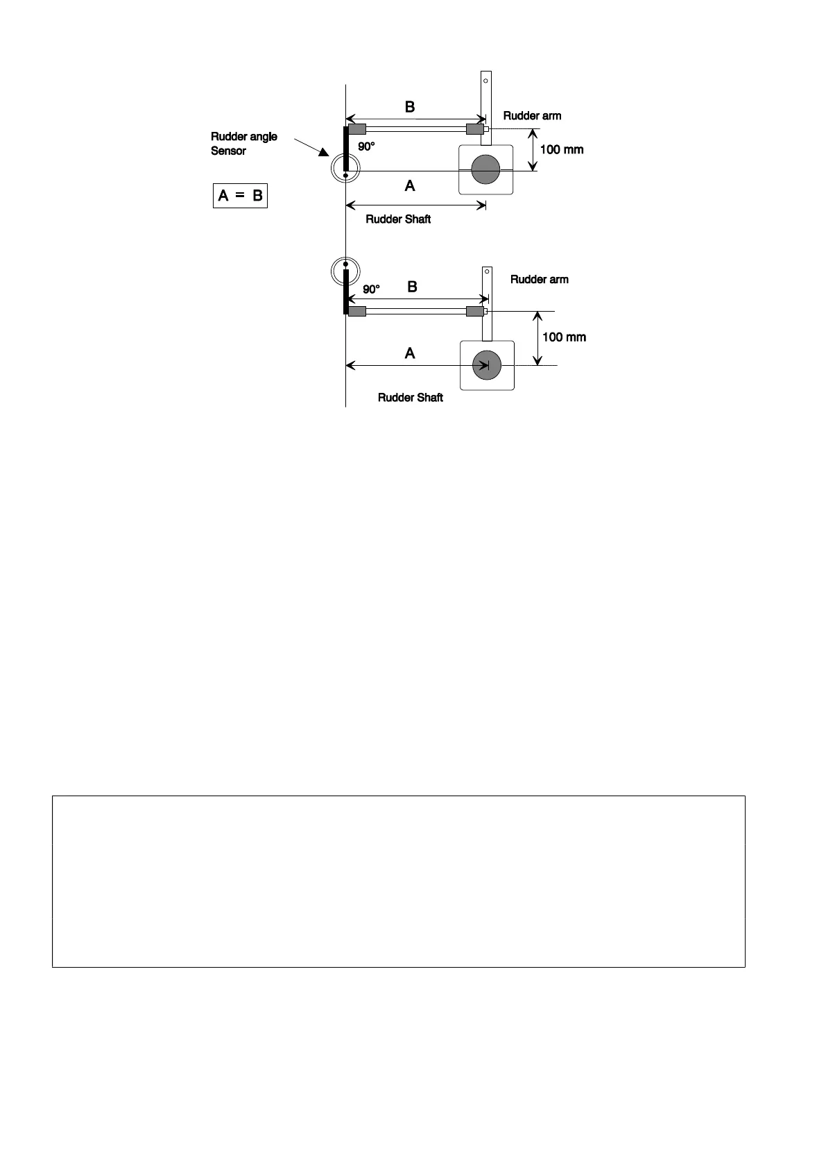
2. Measure precisely the distance A
3. Carefully centre the sensor so that the straight line going by the axis of the sensor arm
and the blocking nut is parallel to the rudder arm.
4. Drill a 7mm hole and mount the threaded connector arm to the rudder arm and the
sensor arm.
5. Then, cut the threaded rod such as value L = A-22mm
6. Mount the tips on the threaded rod, and block them with the counter nuts.
7. Before mounting the rod and tips on the connector arm, test manually your installation :
maintain the tips just above each connector, and move the rudder from Port to
starboard. If the parallelism is good, you can mount the tips on the connector arms.
WARNING :
When the rudder is centred, the rudder arm of the angle sensor must also be centred and
parallel to the rudder arm.
The threaded rod must always be parallel to the linear drive axis. If not, this could seriously
damage the sensor.
The A lenght of the threaded rod must be less than 360mm.
 Loading...