2 of 3
nPP16 ER EFP
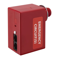
UL-924 EMER. RELAY PACK
FAMILY INSTRUCTIONS
Acuity Brands | One Lithonia Way Conyers, GA 30012 Phone: 800.535.2465 www.acuitycontrols.com © 2018 Acuity Brands Lighting, Inc. All rights reserved. Rev.
01/26/2019 IS-NPP16ER-EFP-004
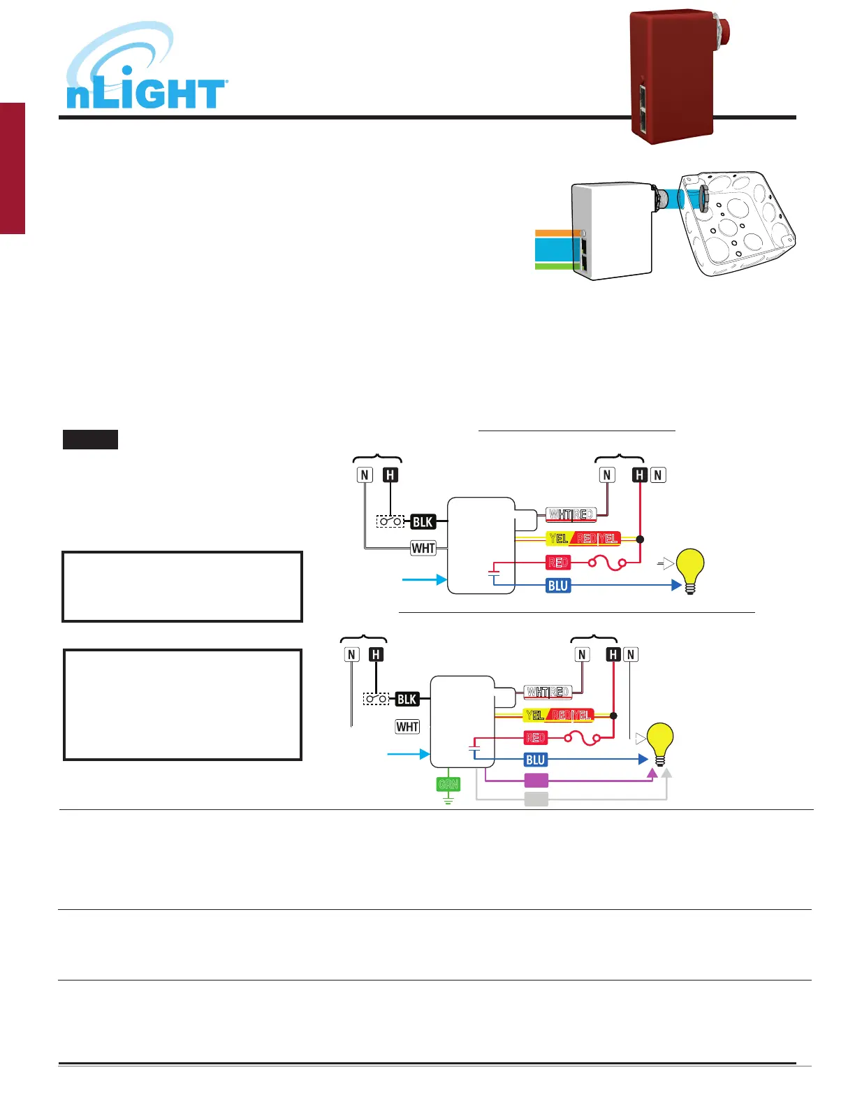
BUTTON
LED
RJ-45 PORTS
• Disconnect or turn off power before installing or servicing the nPP16 ER EFP.
• The nPP16 ER EFP includes a factory-installed fuse holder attached to the red wire. For ease of in-
stallation, pass the lead with the fuse holder through the KO and lock nut first, then pass the other
leads through the KO and lock nut. Care should be taken not to nick the wires while threading
them through the knockout.
• Mount through a ½” knockout in a 4” square or larger steel junction box (deep box recommended)
or luminaire. Secure with supplied lock nut.
• Following the applicable wiring diagram below, connect wires to line voltage feed, neutral, and
load. Relay and power supply must be connected to the same input circuit.
• Fuse holder must be installed with slack in wire leads at all times. Failure to leave slack in wire
leads may cause fuse holder to overheat.
• If applicable, connect low voltage violet and gray dimming wires to 0-10 VDC ballast/driver and
green wire to an approved ground connection. Note wires have 600V rated insulation.
• Interconnect unit (via RJ-45 ports) with other nLight devices in lighting zone using CAT-5e cables.
• Test all wiring for shorts prior to powering up the unit from the circuit breaker, and ensure that
there are no loose or exposed wires that could short to other wires or components. Once wiring is
confirmed, power up the unit from the circuit breaker.
• Once low voltage power is received via the CAT-5e connection, all devices in the zone will automati-
cally begin functioning together according to each device’s defaults.
INSTALLATION INSTRUCTIONS
• Connect to 120VAC or 277VAC feed ONLY.
Cap o unused wire.
• For 347V product, Red wire is 347VAC Emer.
Feed.
• Normal Sense input: 120-277VAC. For 347V
product: 120-347VAC.
CAT-5e
LEGEND
WHT|RED - Emer. Neutral
YEL - 120V Emer. Hot
RED|YEL - 277V Emer. Hot
RED - Emer. Hot (Switched In)
BLU - Emer. Load (Switched Out)
BLK - Norm. Hot
WHT - Norm. Neutral
nPP16 ER
EFP
Normal
(sense only)
OPTIONAL
TEST SWITCH
RED
Emergency
WHT|RED
YEL RED|YEL
YEL RED|YEL
CAT-5e
LEGEND
WHT|RED - Emer. Neutral
YEL - 120V Emer. Hot
RED|YEL - 277V Emer. Hot
RED - Emer. Hot (Switched In)
BLU - Emer. Load (Switched Out)
BLK - Norm. Hot
WHT - Norm. Neutral
VIO - 0-10V Dim (+)
GRY - 0-10V Com (-)
GRN - Earth Ground
nPP16 ER
EFP
Normal
(sense only)
RED
Emergency
WHT|RED
0-10 VDC
Ballast or
LED Driver
VIO
GRY
GRN
OPTIONAL
TEST SWITCH
Diagram for units with a dimming option (-D or -DS sux)
Diagram for non-dimming units
NOTE
T568B pin/pair assignment is recommended for all CAT-5e cables. Unit powers itself but does not provide any bus power to other connected nLight devices. For Supply
Connections, use 14 AWG or larger wires rated for at least 90º C.
For further troubleshooting
guidance, please contact the
Controls Technical Support Team
1(800)-535-2465
Additional nLight devices
do not show power from
nPP16 ER EFP device
• Confirm there is a device that provides bus power in the daisy-chain.
Note that “ER” devices to not supply bus power.
• Confirm line voltage power (120VAC or 277VAC) is present to the nPP16 ER EFP unit
• Confirm line voltage power is connected to the correct line voltage input wire, 120VAC or 277VAC, as identified in the wiring diagram
• Confirm all line voltage wiring connections
• Confirm RJ45 pinout connections
RJ45 LEDs are showing
rapid flash for 1 second,
followed by two blinks
• Confirm there is no debris or bent pins within the RJ45 connections on all devices in the daisy-chain, and that all connectors are
properly snapped into the RJ45 port
• Use a CAT5 cable tester to confirm all cables are properly terminated
• Confirm no CAT5 cables are kinked or held with cable ties that are overtightened
Restore Factory Defaults 1. Press and hold button until LED flashes rapidly
2. Press button 9 times
3. During LED flash back (3 individual flashes), press the button twice
4. LED will flash twice to confirm reset, press and hold button until LED flashed rapidly
5. Press button 9 times. LED wil blink twice to show successful factory reset
TROUBLESHOOTING (NPP16 ER EFP)
DO NOT REMOVE, BYPASS, OR
TAMPER WITH FACTORY-INSTALLED
FUSE HOLDER ATTACHED TO RED
WIRE.
 Loading...