Catalog Number
Notes Type
PRODUCT OVERVIEW
The nLight nPP16 family of power packs is the workhorse of an nLight system, delivering
robust system performance and design versatility for commercial and industrial lighting
control applications. The nPP16 family is capable of switching loads up to 16 Amps via
an internal latching relay designed with robust protection from the harsh switching
requirements of T5 uorescent and LED loads. These power packs also provide nLight system
bus power - up to 40mA from each of its two RJ-45 ports - by transforming Class 1 line
voltage (120/277 VAC or 347 VAC) to Class 2 15 VDC. This power is typically utilized by other
nLight devices within the power pack’s local control zone; however, remaining power is also
made available over the network for Bridges and devices in other zones to utilize.
Besides switching, the nPP16 family has an optional 0-10V dimming output. This output can
be directly wired to 0-10 VDC dimmable ballasts or LED drivers, and is fully isolated internally
from ingress noise or line voltage faults. Models are available with dimming wires running
through the chase nipple (nPP16 D) or out the side of the enclosure (nPP16 DS).
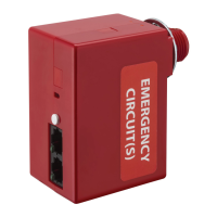
The nPP16 ER and nPP16 D ER version relay packs provide a UL 924 compliant solution for
controlling luminaires powered via an emergency circuit. Packs are wired to both normal and
emergency power feeds. A unit only monitors the normal feed, while the emergency feed
is connected to the line side of its relay. The power feed to emergency lighting is connected
to the load side of the unit’s relay. When normal power is present the relay is free to switch
the emergency power feed as directed by sensors, switches, and schedules. However, if the
normal power feed is lost the nPP16 (D) ER will override its relay closed and set its dimming
output to full bright, thus ensuring emergency lighting is on. During this emergency
operation period, the unit will not allow any switching or dimming to take place regardless
of the presence of an occupancy, daylight, or other control signal. Emergency units power
themselves from the emergency feed they are controlling, but they do not supply bus power
out of the RJ-45 ports, and are often complemented with standard nPP16 power/relay packs
that control a zone’s normal-powered lighting.
To simplify installation, all nPP16 family power packs are designed with an elongated chase
nipple that allows them to be attached directly through a ½” knockout into a junction box or
luminaire.
nLIGHT OPERATION
All nPP16 family power/relay packs are native nLight devices, meaning they are individually
addressable and communicate digitally over an nLight network to integrate with other nLight
enabled devices, such as wall switches, sensors, and photocells. Creation of a local nLight
control zone is done by simply wiring together nLight devices using CAT-5e cabling. When an
nLight zone is linked to an nLight Gateway (nGWY2) - either directly via an nLight network
backbone (nBRG 8) or wirelessly via nWiFi - the zone becomes capable of remote status
monitoring and control with nLight SensorView software.
All nLight switches and sensors can be congured to output on one of 16 local channels or
128 global channels. nPP16 family power/relay packs are congured to follow one or more of
these channels via their tracking channel settings. By default, a standard nPP16 is congured
to follow all occupancy, photocell, and switch commands on Channel 1.
Once powered, units close their relay. If an nLight occupancy sensor is connected, the pack
will automatically start following the occupancy status of the sensor. The factory default
sequence of operation of standard units is Auto On/Auto O. Via the -SA option, Manual
On / Auto O is also available as the factory default operational sequence. Several other
operational sequences are selectable via the unit’s push-button or SensorView software.
If communication is lost between an nPP16 family power/relay pack and all other nLight
devices, the unit will revert back to its default state of relay closed (lights on). All factory
defaults can be changed by using the unit’s push-button or via SensorView software.
1 of 3Sensor Switch 900 Northrop Road, Wallingford, CT 06492 Phone: 1-800.PASSIVE sensorswitch.com/nLight ©2014 Acuity Brands Lighting, Inc. All rights reserved 09/26/14
nPP16
FAMILY
POWER / RELAY PACK w/
OPTIONAL DIMMING and EMERGENCY OPERATION
KEY OPTIONS
DIMMING CONTROL (D, DS)
• Provides dimming outputs to control 0-10 VDC dimmable ballasts or LED drivers
• Follows dimming commands from nLight dimming WallPods, Photocells, Scene
Controllers, and/or SensorView software
• Adds 20 AWG (600V rated) violet & gray wires through chase nipple (D option) or via a
separate side output (DS option)
• Isolated dimming circuitry provides robust network protection from ingress noise or line
voltage faults
EMERGENCY OPERATION (ER)
• Controls luminaires powered via an emergency circuit
• UL924 Listed
• Monitors normal power and overrides relay closed and sets dimming output (if present)
to full bright if normal feed is lost regardless of current state or sensor status
DEFAULT MODE (SA, SA2, SW2, PL T24)
• SA option changes default operating mode to Manual On/Auto O
• SA2 and SW2 change default switch tracking channel to 2
• PA (Partial On) mode changes default operation of dimming units to be Auto On to 50%
• PL T24 option for 120 VAC plug load control. Changes default operation to track only
occupancy sensors (not switches or photocells)
347 VAC (347)
• Allows unit to be powered from and switch 347 VAC.
LOW TEMP/HIGH HUMIDITY (LT)
• Device electronics are coated for corrosion resistance - required for cold storage or
humid areas
• Unit operates down to -40º F/C
OPERATIONAL SETTINGS
Several operational settings for the nPP16 family are available, including:
• Override (On/O/Normal) & Relay Test Mode (Enable/Disable)
• Occupancy, Photocell, & Switch Tracking (Enable/Disable)
• Occupancy, Photocell, & Switch Tracking Channel (1-16 each)
• Idle Time to Dim
• Special Operating Modes:
Manual On to Auto O (Semi-Auto), Auto to (Timed) Override On, Manual to (Timed)
Override On, Manual On to Full Auto, Predictive O
• Occupancy Expiration of Manual O / Timed Expiration of Manual O
• Maintain Dim Level When Vacant
• Occupied Bright Level & Unoccupied Dim Level
• High End & Low End Trim
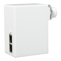
Model #: nPP16 (D)
Model #: nPP16 (D) ER
Note: For information on current monitoring relay packs, see the nPP16 IM series datasheet.