NMC-WOLLARD 2021Truax Blvd., Eau Claire, WI 54703, Phone (715) 835-3151, Fax (715) 835-6625
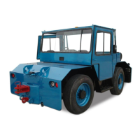
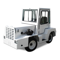
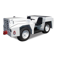
M60 Tow Tractor Manual No. 46050
PAGE 1
CHAPTER 1 GENERAL INFORMATION AND OPERATING INSTRUCTIONS
2 OPERATION
2. OPERATION
Read and understand the Owner’s Manual before operating this
machine. Failure to follow the safety instructions could result in serious injury or death.
To prevent serious injury, all riders must ride in a passenger seat with
the safety belt fastened.
2.1 PRE-OPERATION CHECK
Inspect the tractor for shipping damage. A thorough visual examination will usually
reveal any damage that may have occurred in transit. Report damage to the proper
authorities so that repairs and claims may be made.
The tractor is shipped with all uids except fuel. As a precaution, however, check
all uid levels, brakes, electrical system, engine, steering, axles, and transmission
as described in Chapter 2 and perform the prescribed lubrication.
2.2 UNDERSTAND THE CONTROLS AND INSTRUMENTS
Before driving the tractor, become familiar with all operating controls and
instruments as described below. Then drive the tractor without a tow load until you
can handle the vehicle properly.
2.2.1 Operator’s Controls
1. The gasoline ignition switch is a rotary type marked OFF, IGN (ignition),
and START. The diesel ignition switch is a rotary type marked O (o), R
(run), H (heat), and HS (heat/start).
2. The head and tail light toggle switch controls the two sealed beam
headlights and the tail lights.
3. The rear work light toggle switch controls the rear work lights.
4. The gear shift lever is to the right of the driver. It permits selection of
forward or reverse gears and a neutral position.
5. The accelerator pedal is to the right of the brake pedal and is connected
by mechanical linkage to the throttle body (gasoline) fuel injection pump
(diesel).
6. The park brake lever is to the right of the driver. It must be pushed
forward to disengage the park brake. Tension on the brake cable is
changed by loosening or tightening the knob on top of the brake lever.
7. The service brake pedal is to the left of the accelerator pedal.
AUGUST 31, 2008
Property of American Airlines