User Manual 53User Manual 52
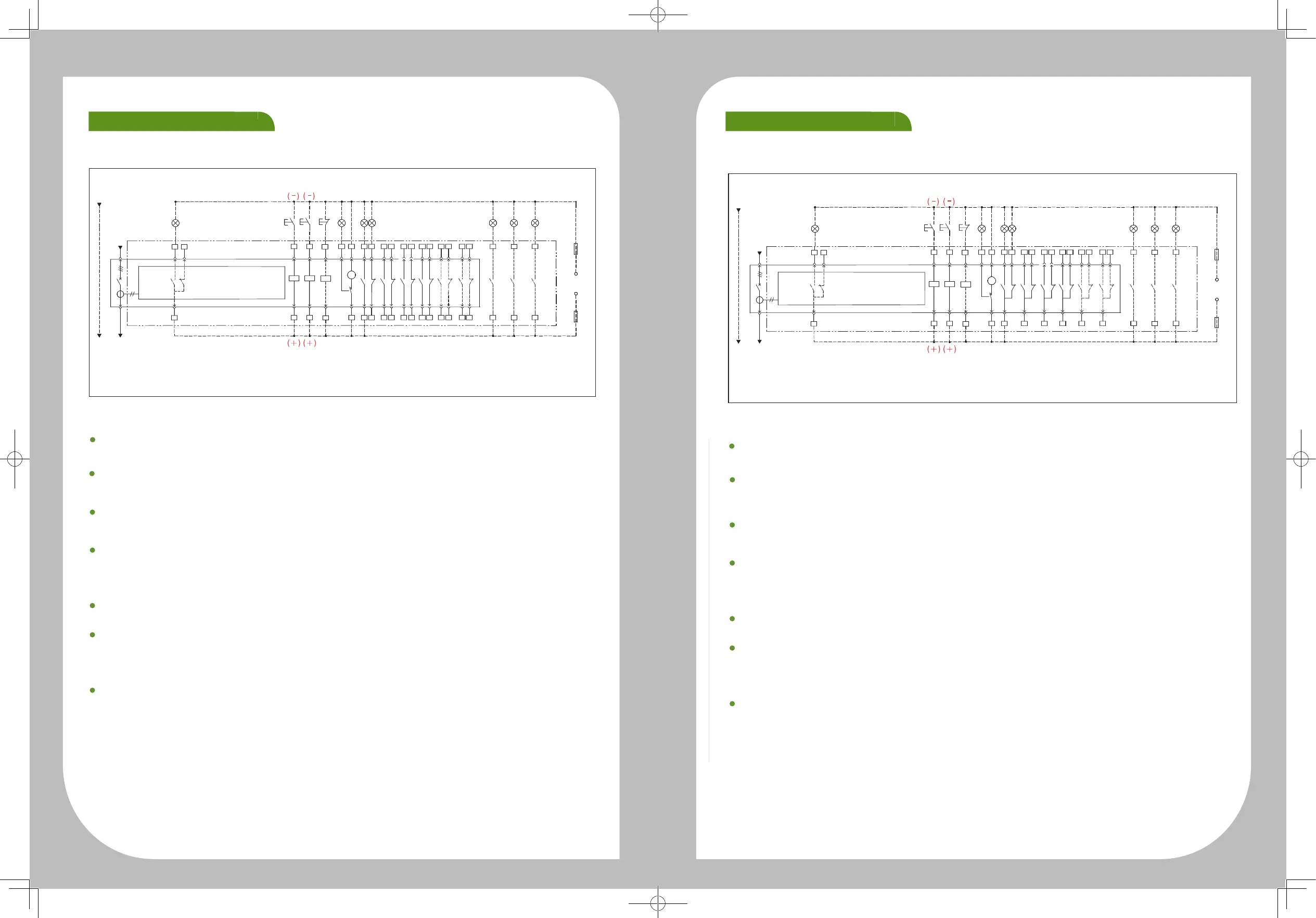
ASD32 Non-automatic switch control circuit referance wiring diagram(4 NO and 4 NC & 6 NO and 6NC auxiliary )
Control circuit wiring
User Manual 31
ASD32 Non-automatic switch control circuit referance wiring diagram(4 NO and 4 NC & 6 NO and 6NC auxiliary )
Spring
charge
indication
when control voltage is DC,please identify positive and negative poles
Ready to
close contact
indication
Ready to close contact indication (optional)
6#,7#,8#: ready to close contact indication;
HL8 signal indicator should be provided by user itself.
N
QF
TA
XT
6 8
32 34
36
37
39
40 42 44 46 48 50 52 54 16
18
20 22 58 61 64
62 655953 15 1938 41 45 4931 33
357
HL8
SB1
SB2
SB3 HL2 HL3 HL4
AX1 AX2 AX3 AX4 AX5 AX6
HL5 HL6 HL7
Opening Closing
Closing
indication
Opening
indication
Auiliary contact - for user
Connecting
positon
indication
Test positon
indication
Disconnecting
positon
indication
FU
FU
Control power
QF - circuit breaker
TA - current transformer
XT - terminal
SA - position switch
SAL - micro switch
FU - fuse
SHT shunt release
31#, 32#: SHT shunt release working power input, if DC working
voltage is used, 31# is positive pole, 32# is negative pole. SB1
opening button should be provided by user itself.
XF shunt release
33#, 34#: XF closing coil working power input, if DC working voltage
is used, 33# is positive pole, 34# is negative pole. SB2 closing button
should be provided by user itself.
UVT undervoltage relasse (optional)
35#, 36#: UVT undervoltage release working power input;
SB3 emergency disconnecting button should be provided by user
itself.
Undervoltage release is within special order range, wiring are not
provided for regular supply.
MD spring charge motor working power
37#, 38#, 39#: MD spring charge motor working power input;
HL2 spring chargr indicator should be provided by user itself.
AX1 - AX6 auxiliary contacts
40# - 55# (AX1 - AX4): 4 groups of auxiliary contacts for regular supply;
15# - 20# (AX5 - AX6): add 2 groups of auxiliary contacts to form
specially ordered 6 groups of auxiliary contacts, no wirings for regular
suuply;
HL3, HL4 status indicators should be provided by user itself.
Withdrawable circuit breker 3-position indicator (optional)
58#, 59#: connecting posation indicator;
61#, 62#: test posation indicator;
64#, 65#: disconnecting position indicator;
HL5, HL6, HL7 signal indicator should be provided by user itself;
this function is only avaiable for specially ordered withdrawable switchs,
no wiring for regular supply.
SHT XF
UVT
SA
MD
43
47 51 55 17 21
ASD32 Non-automatic switch contaol circuit reference wiring diagram(4 groups & 6groups auxiliary )
Control circuit wiring
User Manual 31
ASD32 Non-automatic switch contaol circuit reference wiring diagram(4 groups & 6groups auxiliary )
Spring
charge
indication
when control voltage is DC,please identify positive and negative poles
e
Secondary circuit wiring
Ready to
close contact
indication
Ready to close contact indication (optional)
6#,7#,8#: ready to close contact indication;
HL8 signal indicator should be provided by user itself.
N
QF
TA
XT
XT
6 8
32 34
36
37
39
40 42 43 45 46 48 49 51 52 54 55 13 58 61 64
62 655950 53 5638 41 44 4731 33
357
HL8
SB1
SB2
SB3 HL2 HL3 HL4
AX1 AX2 AX3 AX4 AX5 AX6
HL5 HL6 HL7
Opening Closing
Closing
indication
Opening
indication
Auiliary contact - for user
Connecting
positon
indication
Test positon
indication
Disconnecting
positon
indication
FU
FU
Control power
QF - circuit breaker
TA - current transformer
XT - terminal
SA - position switch
SAL - micro switch
FU - fuse
SHT shunt release
31#, 32#: SHT shunt release working power input, if DC working
voltage is used, 31# is positive pole, 32# is negative pole. SB1
opening button should be provided by user itself.
XF shunt release
33#, 34#: XF closing coil working power input, if DC working voltage
is used, 33# is positive pole, 34# is negative pole. SB2 closing button
should be provided by user itself.
UVT undervoltage relasse (optional)
35#, 36#: UVT undervoltage release working power input;
SB3 emergency disconnecting button should be provided by user
itself.
Undervoltage release is within special order range, wiring are not
provided for regular supply.
MD spring charge motor working power
37#, 38#, 39#: MD spring charge motor working power input;
HL2 spring chargr indicator should be provided by user itself.
AX1 - AX6 auxiliary contacts
40# - 51# (AX1 - AX4): 4 groups of auxiliary contacts for regular supply;
52# - 56# (AX5 - AX6): add 2 groups of auxiliary contacts to form
specially ordered 6 groups of auxiliary contacts, no wirings for regular
suuply;
HL3, HL4 status indicators should be provided by user itself.
Withdrawable circuit breker 3-position indicator (optional)
58#, 59#: connecting posation indicator;
61#, 62#: test posation indicator;
64#, 65#: disconnecting position indicator;
HL5, HL6, HL7 signal indicator should be provided by user itself;
this function is only avaiable for specially ordered withdrawable circuit
breakers, no wiring for regular supply.
SHT XF
UVT
SA
MD
 Loading...