•
VMMC: 2.85 V (from level shifter)
•
VIO: 1.8 V (from AVILMA)
The card removal is detected by a push detect switch.
User interface
Display module
The interconnection between the LCD module and the engine is implemented with a 24-pin board-to-board
connector.
The LCD module does not require any tuning in service.
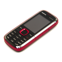
Keyboard
Table 8 Key signal matrix
GENIO ROW Col_0
(GENIO-39)
Col_1
(GENIO-40)
Col_2
(GENIO-41)
Col_3
(GENIO-42)
Col_4
(GENIO-43)
32 ROW0 Left SK Left Right SK Right Volume +
33 ROW1 Send UP Action Down Volume -
34 ROW2 1 4 7 * Forward
35 ROW3 2 5 8 0 Start/Stop
36 ROW4 3 6 9 # Rewind
Backlight and illumination
There is backlight illuminating for the display consisting of 2 LEDs.
The keypad is side lit by 4 LEDs with film lightguide.
The sidekey is top lit by 3 LEDs.
RM-495; RM-496
System Module
Issue 1 COMPANY CONFIDENTIAL Page 5 –11
Copyright © 2008 Nokia. All rights reserved.

 Loading...