CCS Technical Documentation 5 - Disassembly Instructions
Company Confidential NMM-3
Issue 1 (11/2003) Copyright 2003 Nokia Corporation. Page 5-15
Company Confidential
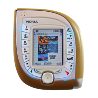
2. Assemble the UI PWB Module onto
the Engine shield ensuring the shield
is kept flat and not distorted or bent.
The PWB must be LED’s up and care
must be taken not to touch the board
to board connector pads.
Note: Ensure the datum pins on the
shield are not deformed.
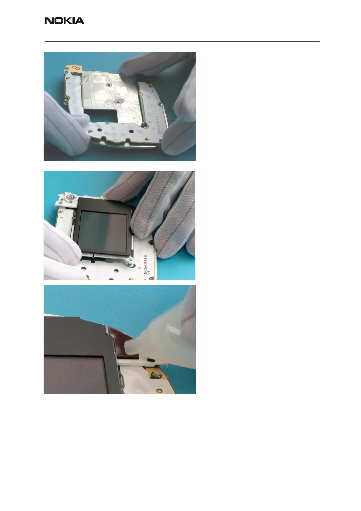
3. Assemble the LCD module onto the
UI shield assembly, ensuring the clip
at the top & middle of the frame near
the ear piece is assembled first and
then the bottom frame location hole
is assembled over the shield pin.
Note: Ensure the LCD is kept flat at
all times and only ever handled from
the sides. The protective tape must be
kept on the LCD during handling and
assembly.
4. Clip the male LCD connector on
the LCD module into the female LCD
connector on the UI PWB, ensuring to
align the devices first. The connector
should snap into place.
Note: The connector must be assem-
bled keeping it flat and applying even
pressure across the top of the rigi-
diser.
2
3
4
 Loading...