Nokia C2-02 /C 2-07 (RM-692/RM-693)
Nokia C2-03 /C 2-06/C 2-08 (RM-702)
L1L2 Service Manual
Co nf id e nt ial | Co p yrig ht © 2011 Nokia | A ll rights reserved
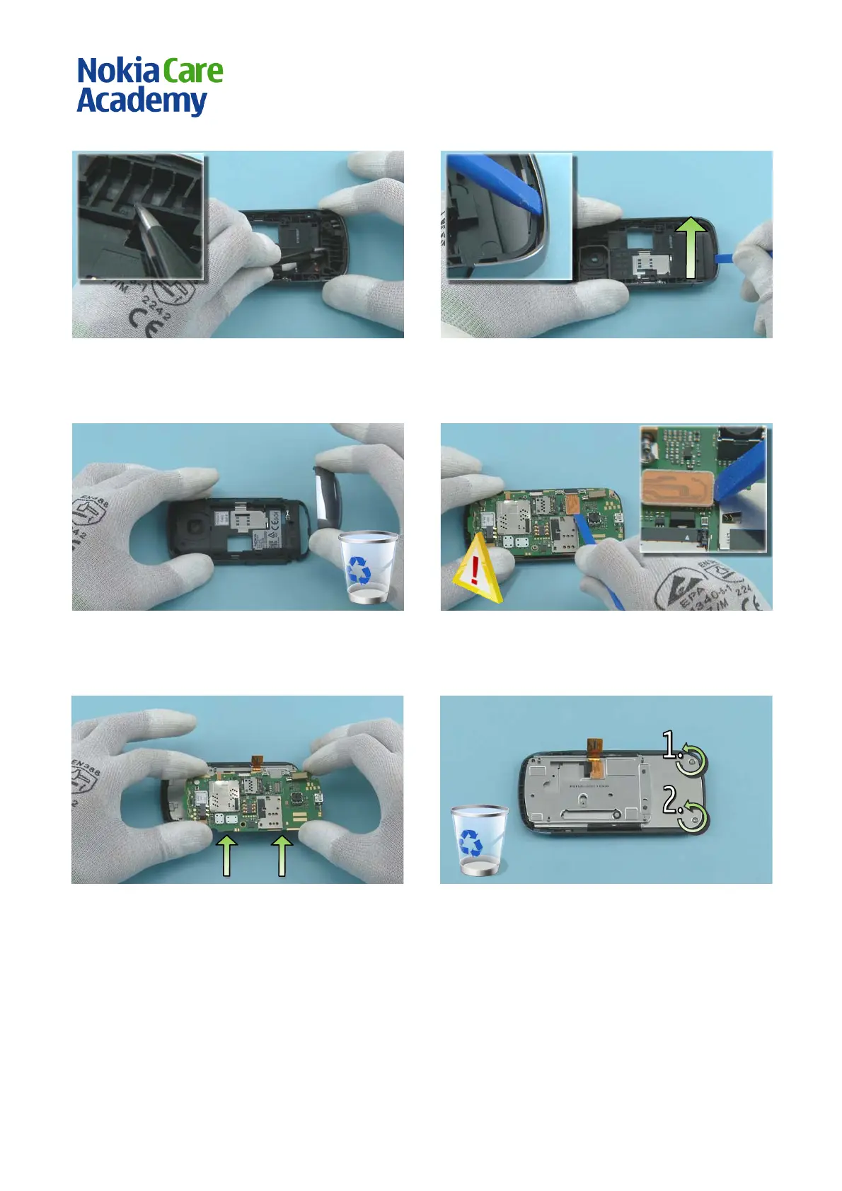
19) Insert the tweezers underneath the ANTENNA
MODUL E to lift it up and remove it.
20) Release the B-COVER DECO by sliding the SS-93
between the D-COVER and the B-COVER DECO.
21) Remove the B-COVER DECO. Do not use it again.
Discard it.
22) Release the UI FLEX connector with the SS-93. Be
careful not to damage the connector or any nearby
components.
23) Lift up the ENGINE BOARD carefully.
24) Unscrew the two TORX+ size 4 screws in the
order shown. Do not use them again. Discard them.
 Loading...