Check list
Check list
Power supply wires are connected correctlyPower supply wires are connected correctly
Cabling (continued)Cabling (continued)
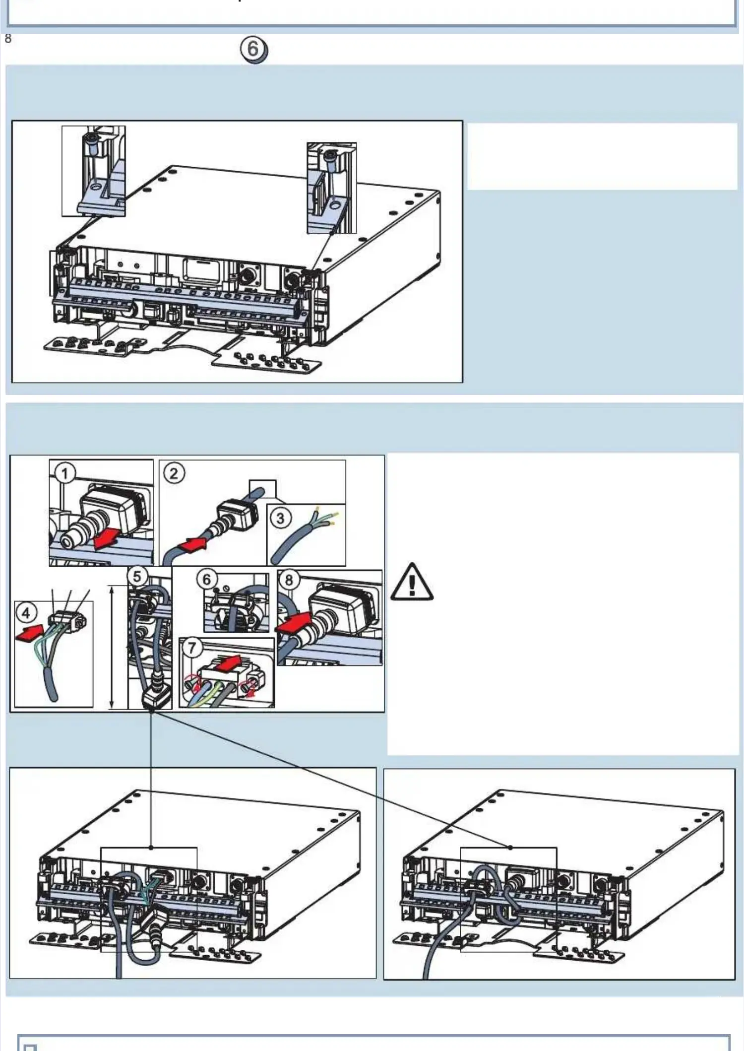
Strain relief barStrain relief bar
I I tthhee
(T15)(T15)
nsnstaltall l strstrain ain relrelief ief babar ar and nd scrscrew ew it it witwith th twowo
MM5 5 ssccrreewwss..
AC power cableAC power cable
22
00
mm
mm
((
00
..
77
99
ii
nn
..
))
1. Remove the IP boot from the module.1. Remove the IP boot from the module.
2. Thread the cable through the IP boot.2. Thread the cable through the IP boot.
Strip the cable shielding and peel the wiresStrip the cable shielding and peel the wires
((NNOOTTEE: : sshhoouulld d bbe e lloonnggeer r tthhaan n ootthheerrss))
. Ins. Insert wert wires ires to thto the Ae AC inpuC input cont connectnectoror
3. 3. ..
groundingrounding g wirewire
4 4 iin n ..
(N - Neutral, PE - Earth, L - Line)(N - Neutral, PE - Earth, L - Line)
- - --
WARNING! Risk of power supply failure and,WARNING! Risk of power supply failure and,
in rare cases, of short circuit.in rare cases, of short circuit.
Check that the polarity is correct accordingCheck that the polarity is correct according
to the markings on the cable.to the markings on the cable.
. Thread the cable around the strain relief bar and. Thread the cable around the strain relief bar and
ththrorouuggh h tthe he ststraraiin n rerellieief f clclaamp eamp eave ve 220 0 mm
f f tthhe e ccaabblle e ..
. Fix the clamp's screws.. Fix the clamp's screws.
. Insert. Insert AC input conneAC input connector and fix its screws.ctor and fix its screws.
. Push the IP boot firmly in place.. Push the IP boot firmly in place.
55
; ; l l aabboouut t 0 0 m m ((77..887 7 iinn..))
o o ffoor r ccoonnnneeccttiioon n ppuurrppoosseess
NOTE: the maximumNOTE: the maximum AC wire cross-seAC wire cross-sectional area isctional area is
2.5 mm 2.5 mm (A(AWG 3).WG 3).
6 6 UUsse e a a TT110 0 ssccrreewwddrriivveerr..
77
88
22
 Loading...