CablingCabling
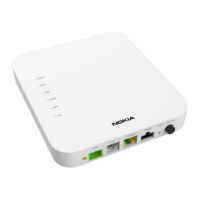
1. Connect the grounding cable to the grounding1. Connect the grounding cable to the grounding
popoint int anand d scrscrew ew witwith h M5 M5 (to(torx rx 25) 25) scrscrewew..
2. 2. (Opti(Optionalonal) Se) Secure cure the the cablcable wie with a th a cablcable e ..
it init in
tietie
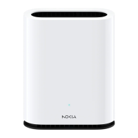
1. Remove the IP seal1. Remove the IP seal
2. 2. InsInsert ert SFSFP P tratranscnsceiveiverer..
3. 3. CoConnnnecect t opoptiticacal l cacablble.e.
44
. Route the cable to the left and secure it with. Route the cable to the left and secure it with
dedicated NSN strain relief.dedicated NSN strain relief.
..
thethe
thethe
..
55
a a UUsse e a a TT2200
screwdriver.screwdriver.
Push the connector seal firmly in place.Push the connector seal firmly in place.
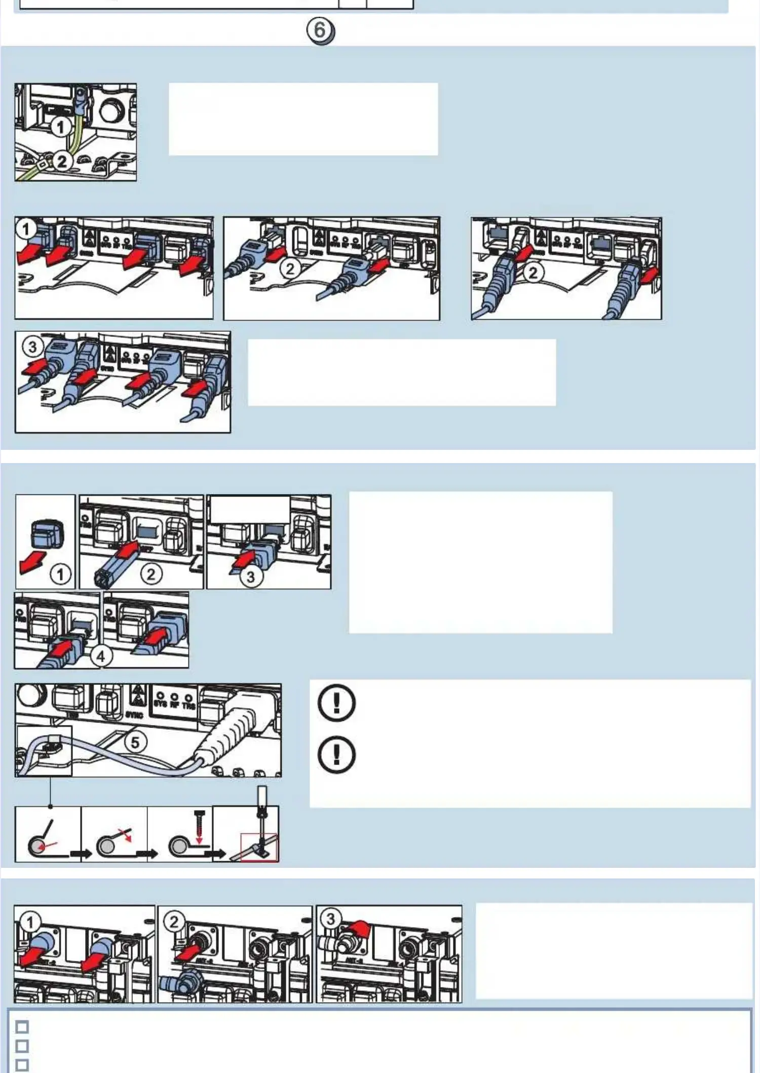
1. Remove the covering caps.1. Remove the covering caps.
2. Connect antenna cables2. Connect antenna cables
33. . TTiigghhtteen n tthhe e tto o NNm m ( ( . . llb b f f ))
..
ccaabbllees s 11..2 2 0 0 889 9 t t ..
Clean with swab orClean with swab or
wwipipe e alalc oc ohohol.l.s s wwiitthh
GroundingGrounding
Optical transmission cabling (SFP)Optical transmission cabling (SFP)
NOTICENOTICE: Make sure that: Make sure that
the optical cable connectorsthe optical cable connectors
have been cleaned.have been cleaned.
NOTICENOTICE
: : Use only straUse only straight or left-beight or left-bent optical cabnt optical cables andles and
always route the cables leftwards.always route the cables leftwards.
NOTICENOTICE
: Do not bend optical cables beyond the minimum: Do not bend optical cables beyond the minimum
radius ofradius of
70 mm70 mm
::
- - (2(2.7.76 6 inin.).), , whwhen en cacablble e didiamameteter er is is 7 7 mm mm (0(0.2.28 8 inin.).)
- 50 mm (1.97 in.), when cable diameter is 5 mm (0.20 in.)- 50 mm (1.97 in.), when cable diameter is 5 mm (0.20 in.)
Antenna cablingAntenna cabling
-7--7-
The optical cable connectors are cleaned.The optical cable connectors are cleaned.
The optical cable is properly installed and the minimum bending radius is not violated.The optical cable is properly installed and the minimum bending radius is not violated.
DouDouble ble checheck ck thathat t corcorrecrect t optopticaical l intinterferface ace is is insinstaltalledledtthhe e ..
1. Remove the IP seal.1. Remove the IP seal.
2. Pu2. Put the t the cablcable fire firmly mly (for (for LMP LMP and and TRS tTRS till iill it clit clicks)cks)
3. Push the connector seal firmly in place.3. Push the connector seal firmly in place.
in in ..
Cabling rule for EAC, LMP, TRS, and SYNCCabling rule for EAC, LMP, TRS, and SYNC
 Loading...