Nokia N8-
RM-596
Service Manual Level 1&2
24 Confidential | Copyright © 2010 Nokia | All rights reserved Version 3.0
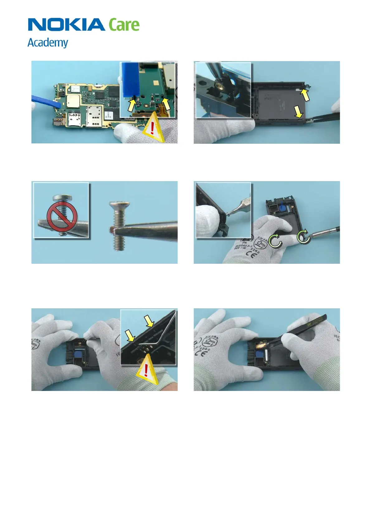
7) Press the SUB PWB carefully with the SS-93. Make
sure the two clips shown are locked.
8) Insert the two FIXING NUTS.
9) Note that there are two different TORX+ size 4
screw heads used in this device. The first two screws
are countersunk heads.
10) Hold the FIXING NUTS in place with your finger.
Tighten the two TORX + size 4 screws until the FIXING
NUTS stay in place. Do not tighten them completely!
If the screws are tightened too much the BOTTOM
COVER cannot be assembled.
11) Place the SIDE SWITCH with the tweezers. Use the
dental tool to lever the SIDE SWITCH under the two
shown clips. Be careful not to injure yourself with
the sharp end of the dental tool!
12) Place the FLASH MODULE with the tweezers.

 Loading...