The AM43 can also be used without the USB connection. To connect to a computer or other device with an RS-232 port,
connect to the OUT terminal as shown. To connect the OUTh signal to an RS-232 input, use only the OUTh+ terminal and
leave the OUTh - terminal disconnected. Figure 3 shows the connection. An RS232 interface can also be directly connected
to OUT or TLK in a similar fashion
Driver Software Installation (Windows NT,2000,XP). USB operation requires a USB Serial Port driver be installed.
Updates to these procedures may be found on the ‘readme.txt’ file on the supplied CD-ROM.
1) If using Microsoft VISTA, disconnect your PC from the Internet.
2) Apply DC power to AM43. Disconnect or turn off all inputs.
3) Insert “AM43 Driver Disk” into disk drive of computer.
4) Connect USB cable from your PC to the AM43.
5) When the “New Hardware Wizard” window appears, DO NOT let “Windows” search for the Driver. (You will select
the location).
6) Continue on through the Wizard and select “Install from specific” location when that option appears.
7) Point the Wizard to your CD-Rom “Drivers” directory and continue. Ignore warning message about “Digitally
Signed Driver”
8) When finished, your AM43 is ready to use with your PC.
Software driver installation is complete. To determine which COM port number was assigned to the USB serial port, look
under Windows “Device Manager, “double click ports (COM and LPT), and look for “USB Serial Port (COM #)”. If any
problems occur, please reference the “Readme.txt” file on the “AM43 Driver CD” installation disk.
3. OPERATION
Once the AM43 is installed and power is applied, the unit begins operating automatically. A flashing green LED indicates
data is being received by one or more of the inputs. NMEA 0183 sentences sent by the PC (via USB) will cause the red LED
to flash. Any errors in the data will cause a half-second yellow flash. Any reconfiguration of the AM43 must be done
through the USB connection and a simple terminal program (see Appendix A).
Status LED. A multicolor LED sits in a recess on top of the AM43. The colors and their meaning are summarized in Table
2. The LED will only show one color at a time as determined by its priority. Yellow has highest priority to show an error
has occurred. Red has next highest priority and will be seen when data is sent to the TLK output. Green will only show if
neither of the other colors is displayed and data is received by an input.
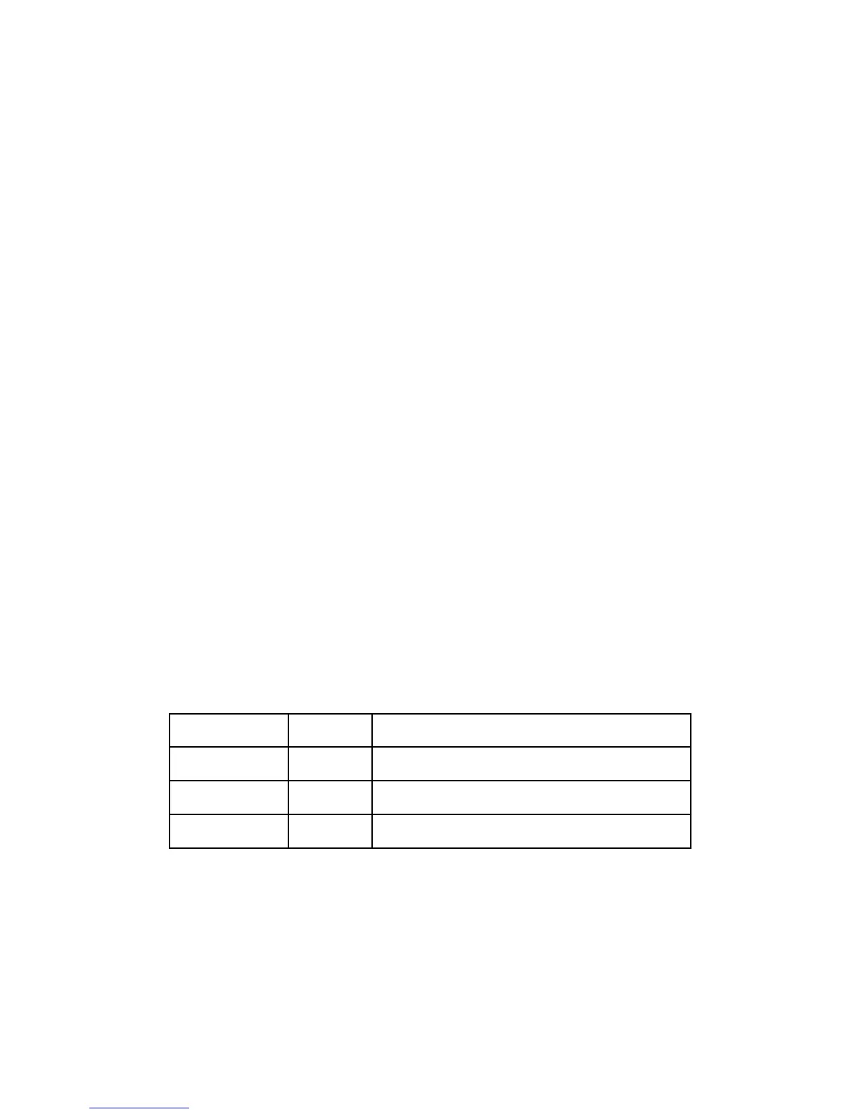
Table 2. LED Status Meanings
Color/State Priority Meaning
Yellow
Steady ~ 1/2 sec
highest
An error has occurred, and an error identification
sentence is being sent to the PC.
Red
Flickering
middle
A valid sentence from the PC (via USB) is being sent
to the TLK output.
Green
Flickering
lowest
A valid sentence from one of the four inputs is being
sent to the outputs.
Whenever the yellow LED is displayed, an error message is sent to the USB interface. The yellow color remains lit for
approximately ½ second. This makes it easier to discriminate from the red color. Refer to “Troubleshooting” (section 4) for
more about the error messages.
.
Data Combining. Combining data from marine navigational instruments is the primary function of the AM43. Under the
NMEA 0183 Standard, all data is transmitted as ASCII characters assembled into specific sentences. The format of every
sentence is defined in the Standard.
Every sentence begins with a dollar sign ($) and ends with a carriage return and linefeed, (<CR><LF>). Immediately
following the “$” is a five character identifier which defines the type of instrument and the specific sentence being sent.
Following the identifier are data fields separated by commas.
 Loading...