7
www.norcold.com
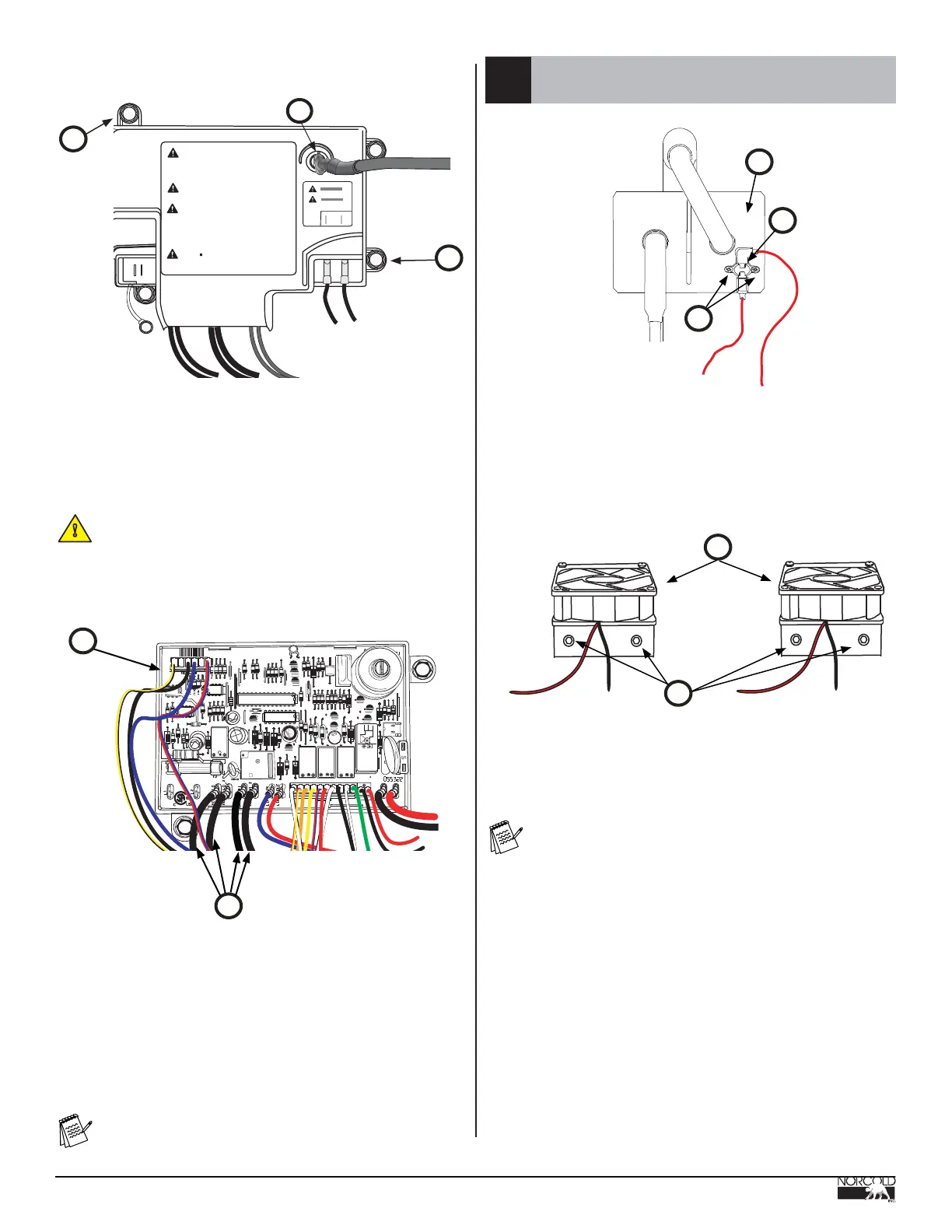
A. Power board
B. Cover screws
C. Igniter wire
D. Heater wires
Disassemble, cont’d.
Caution! Pull gently when disconnecting igniter wire.
Failure to comply can cause permanent damage to power
board.
2. Carefully remove connector of igniter wire (Fig.9.C) from power
board (Fig.10,A). Do not pull directly on wire.
!
Fig. 9 - Power Board
Fig. 10 - Exposed Power Board
NOR000229A
D
A
100 B
ANSI
Z21. 2
JW5
RT424F12
12V
05-43
07
3
D5
R50
R49
07
3
07
3
07
3
4
C
Q3
4
C
D8
CPC - E
94 V - 0
GND
12VDC
Potter & Brumfield
T7CS1D2-05
5VDC
0544
700514
5A@120VAC
CHINA
D3
c
4
D6
3
07
R28
R 3
D13
07
3
R39
D1
N
M
07
3
1237
0301
9
8
4
5
3
K3
R25
R27
R26
R29
C8
7
4
R 1
2
Potter & Brumfield
T77V1D10-09
CHINA
CHINA
10A@120VAC
700514
10A@120VAC
Potter & Brumfield
T77V1D10-09
30VDC RES.
30VDC RES.
700514
D4
R37
R34
4
6
5
D 12
D 11
Z3
C 1
Potter & Brumfield
T77V1D10-09
CHINA
10A@120VAC
30VDC RES.
700514
JW4
JW6
D2
R9
R7
R24
R46
R4
R5
R23
R20
R18
R21
R21
JW7
JW9
JW10
JW8
R36
R41
R45
JW2
R441
R8
R10
JW3
R6
R40
R43
R42
R2
R38
R47
R30
R48
R35
R33
U1
LP1
Q1
Q2
Q6
C9
D10
R11
R12
C7
R16
R15
R17
R19
R13
R22
R32
R31
Z2
D7
R14
U4
C3
C5
U3
U6
JW11
Z4
CHINA
700514
10A@120VAC
Potter & Brumfield
T77V1D10-09
30VDC RES.
P2
P1
P3
P3
3. Remove power board cover screws (Fig.9,B) (2x); remove cover.
4. Disconnect heater wires (Fig.10,D) at the power board.
• AC_HT_LO (Black) - Heater 1
• AC_HT_LO_2 (Black) - Heater 2
• AC_HT_HI (Black) - Heater 1
• AC_HT_HI_2 (Black) - Heater 2
Note: Heaters are contained in canister located on back
right side of refrigerator.
2.8
Remove Fans
NOR0002221A
B
C
A
Fig. 11 - External Fan Thermostat
A. External Fan thermostat
B. Thermostat screws
C. Condenser
D. Fans
E. Fan screws
NOR000222A
D
E
Fig. 12 - Fan Mounting
WARNING
: High voltage can cause servere injury
and death. ONLY qualified RV service techincians
are autorized to remove this cover. Do not allow leak detecting
solutions to touch the electrical components. Many liquids are
electrically conductive and can cause a shock hazard, electical
shorts, and in some cases fire.
CAUTION: 12VDC supply connections are for low
voltage direct current only. DO NOT connect 120 or
240 VAC.
MISE EN GARDE : Le courant à haute tension peut
causer des blessures graves et la mort. SEULS les
techniciens agréés pour véhicules de plaisance sont
autorisés à ôter ce couvercle Ne pas laisser la solution de
détection des fuites entrer en contact avec les composants
électriques. Beaucoup de liquides son conducters
d'électricite et peuvent préseter des danger d'électrucution,
de courts-circuits et parfois d'incendie
ATTENTION : les raccords à courant 12 V c.c. sont
prévus exclusivement pour le courant continu à basse
tension. NE PAS le brancher au courant à 120 ou 240 V c.c.
ART02078-1
C
B
B
1. Remove fan thermostat screws (Fig.11,B) (2x); remove thermostat
(Fig.11,A). Save all parts.
Note: Disconnecting wires from thermostatic switch not
required.
2. On back of refrigerator, remove mounting screws (Fig.12,E) (4x)
from the two (2) upper fans and the lower fan; remove fans and lay
to left side of refrigerator. Do not unplug fan wiring.
3. Cut the cable tie holding the wiring and the icemaker waterline so
that the fans and wiring can be positioned on the left side of the
refrigerator out of the way.
 Loading...