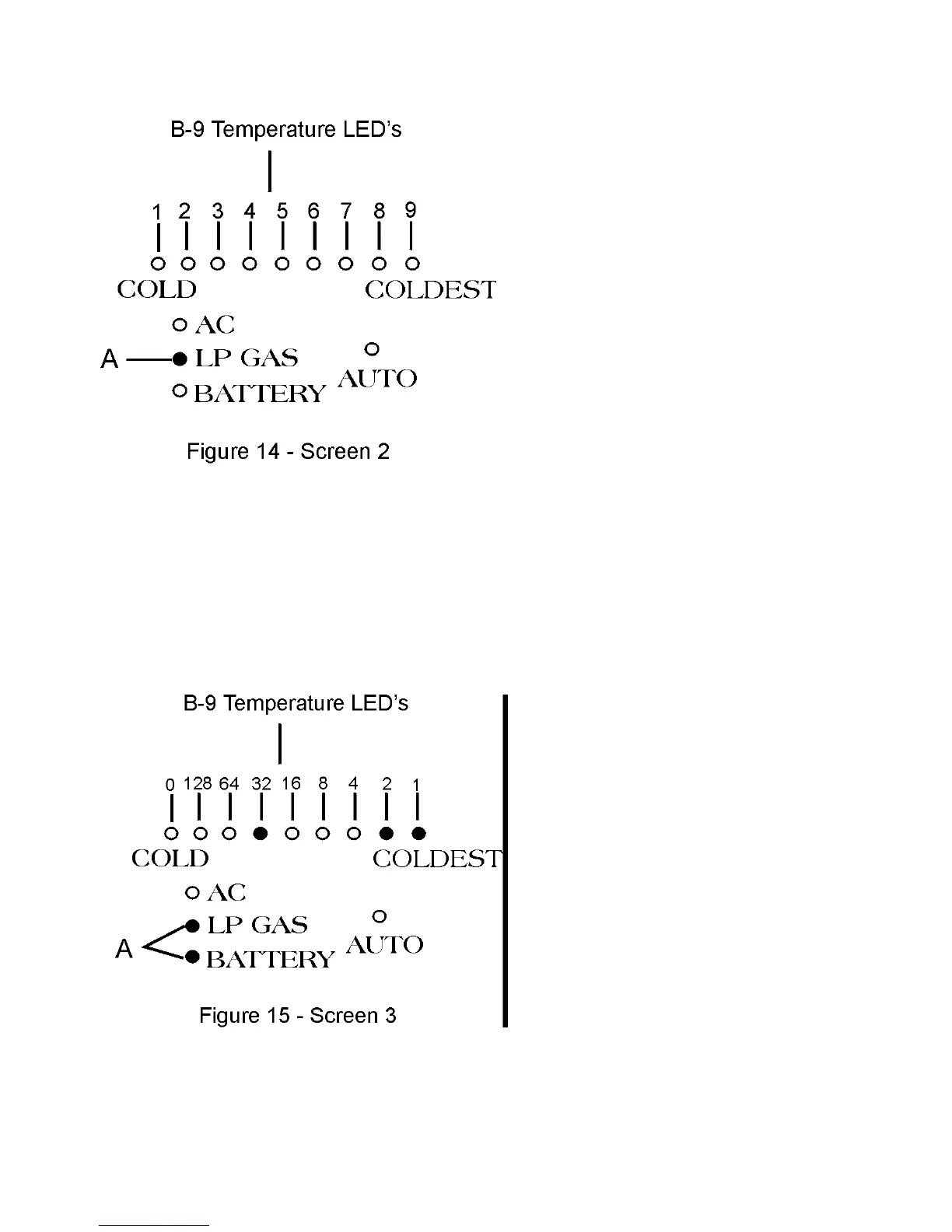
On this screen, the refrigerator control illuminates
LED’s which are real time indication of control activ-
ity.
A - Identifies information screen.
1 - Not Applicable
2 - Not Applicable
3 - Not Applicable
4 - ALL modes of operation, LED on signifies that
the control temperature sensing circuit is not satisfied
and is calling for cooling.
5 - AC Electric mode, LED on signifies that AC
voltage is present to AC heater and within specifica-
tions (108 VAC min. - 132 VAC max.).
6 - LED on signifies current operating mode is AUTO.
7 - LED on signifies current operating mode is AC
electric.
8 - LED on signifies current operating mode is LP
GAS.
9 - LED on signifies current operating mode is BAT-
TERY (DC electric).
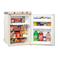
Screen No. 3 - Fin Temperature
Sensed by Thermistor
The thermistor is mounted on the 11th cooling fin
from the right and monitors the refrigerator cabinet
temperature.
A - Identifies information screen.
B - The temperature will be displayed in
°
F on the 9
LED TEMP SET display as shown in Figure 15. Each
LED is assigned a number. To determine cooling fin
temperature, add numbers above illuminated LED for
fin temperature.
Shown: 32 +2+1= 35
°
F.
The following verifies thermistor functionality:
1 - Remove thermistor from fin and immerse thermis-
tor end in ice water. The numerical result (tempera-
ture) should be between 29
°
F and 35
°
F
.
2 - Remove thermistor end from ice water and hold in
hand. The temperature should rise.
If temperature does not fall or rise when performing
the steps above, replace thermistor.
25