EasyManua.ls Logo

Norcold 9182 User Manual

Norcold 9182
36 pages
To Next Page IconTo Next Page
Page #1 background imageLoading...
Page #1 background image
900 & 9100
Series
Service Manual & Parts List
for Models
9182 9183
9162 9163
982 983
962 963
Contents
Safety Information . . . . . . . . . . . . . . . 1
Introduction . . . . . . . . . . . . . . . . . . . 2
Specifications . . . . . . . . . . . . . . . . . . 3
Operating Controls . . . . . . . . . . . . . . . 5
Operating Sequence . . . . . . . . . . . . . . 6
Alphanumeric Codes-900 Series . . . . . . . . 7
Flashing LEDs-9100 Series-
(Diagnostic Indicators) . . . . . . . . . . . . . 11
Diagnostics Fault Indicators-900 & 9100 Series 13
Step-by Step Trouble Shooting . . . . . . . . . 15
Internal Control Information - 900 Series . . . . 19
Internal Control Information - 9100 Series . . . 24
Diagnosing Cooling Problems . . . . . . . . . . 29
Component Check-Out Procedures . . . . . . . 31
Procedure for Cleaning Cooling System Flue . . 33
Fuse Replacement Procedure . . . . . . . . . 34
Wiring Pictorials . . . . . . . . . . . . . . . . . 35
618526C (96-05)
Question and Answer IconNeed help?

Do you have a question about the Norcold 9182 and is the answer not in the manual?

Norcold 9182 Specifications

General IconGeneral
BrandNorcold
Model9182
CategoryRefrigerator
LanguageEnglish

Summary

Safety Information

Introduction

Purpose

Manual provides service info for experienced repair technicians.

Parts

Use genuine Norcold replacement parts for reliability and performance.

Technical Support

Contact for assistance when manual doesn't resolve issues.

Specifications

Operating Controls

900 Series Front Display Panel

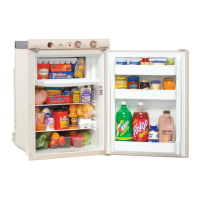
Details controls and display for the 900 series model.

9100 Series Front Display Panel

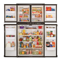
Details controls and display for the 9100 series model.

Operating Sequence-900 and 9100 Series

Auto Mode

Explains automatic energy source selection based on availability.

Manual Mode

Describes how to manually select operating modes.

LP GAS Mode Operation

Details the ignition cycle and operation for LP gas.

Description of Alphanumeric Codes for 900 Series (Diagnostic Indicators)

A1-LP Gas Ignition Failure

Indicates burner ignition failure on start-up or re-ignition.

A2-LP Gas Re-Ignition Failure

Indicates gas failure to re-ignite during normal operation.

A3-Fresh Food Compartment Door Ajar

Alerts owner to an open fresh food compartment door.

Description of Alphanumeric Codes for 900 Series (Diagnostic Indicators)

A4-AC Mode Selected, AC Power Not Available

Indicates AC mode selected but no AC power available.

A5-AC Input Voltage Too Low

Indicates AC input voltage is below acceptable range.

A6-AC Input Voltage Too High

Indicates AC input voltage is above acceptable range.

Description of Alphanumeric Codes for 900 Series (Diagnostic Indicators)

A7-DC Input Voltage Too Low

Indicates DC input voltage is below acceptable range.

A8-DC Input Voltage Too High

Indicates DC input voltage is above acceptable range.

C1-Burner Failed Ignition and DC Heater Failed

Burner ignition and DC heater failure for 3-way models.

Description of Alphanumeric Codes for 900 Series (Diagnostic Indicators)

C2-AC Heater Output Fault

Control senses AC heater current when it should be OFF.

C3-DC Heater Output Fault

Control senses DC heater current when it should be OFF.

C4-3-Way Models Only-DC Heater Failed Open

DC voltage supplied but heater not drawing current.

Description of Alphanumeric Codes for 900 Series (Diagnostic Indicators)

C5-Back-Up Operating System

Thermistor failure leads to backup cooling mode.

C6-AC Heater Failed Open

AC voltage supplied but heater not drawing current.

C7-Flame Sense Circuit Failure

Indicates a failure in the flame sense circuit.

Description of 9100 Series Flashing LED's (Diagnostic Indicators)

Flashing LP Gas LED-All Models

LP Gas LED flashes for burner ignition failure.

Flashing AC LED-All Models

AC LED flashes for AC power availability issues.

Flashing Battery LED-All Models

Battery LED flashes for DC input voltage issues.

Description of 9100 Series Flashing LED's (Diagnostic Indicators)

All LED's Flashing-3 Way Models Only

All LEDs flash for burner/DC heater failure.

All LED's Flashing-All Models

All LEDs flash for AC heater output fault.

Flashing Temperature Setting LED-All Models

Temp setting LEDs flash for backup operating system.

900 & 9100 Series Diagnostic Fault Indicators & Corrective Actions

A1 - LP Gas Ignition Fault

LP Gas ignition failure on start-up or re-ignition.

A4 - AC Mode Selected, AC Power Not Available

AC mode selected, but no AC power is available.

A5 - AC Input Voltage Too Low

AC input voltage is too low for operation.

900 & 9100 Series Diagnostic Fault Indicators & Corrective Actions

A6 - AC Input Voltage Too High

AC input voltage is too high for operation.

A7 - DC Input Voltage Too Low

DC input voltage is too low for operation.

A8 - DC Input Voltage Too High

DC input voltage is too high for operation.

Section 1 - No Display on Display Panel

Section 2 - LP Gas Ignition Failure & Re-Ignition Failure

Troubleshooting LP gas ignition and re-ignition problems.

Section 3 - Fresh Food Compartment Door Ajar

Corrective actions for an open refrigerator door.

Section 4 - AC Mode Selected, AC Power Not Available

Troubleshooting when AC mode is selected but power is absent.

Section 5 - AC Input Voltage too Low

Section 6 - AC Input Voltage too High

Corrective actions for high AC input voltage.

Screen 7 - DC Input Voltage too Low

Corrective actions for low DC input voltage.

Section 8 - DC Input Voltage too High

Corrective actions for high DC input voltage.

Section 9 - Burner Failed Ignition and DC Heater Failed - 3 Way Models Only

Section 10 - AC Heater Output Fault

Corrective actions for AC heater output fault.

Section 11 - DC Heater Output Fault - 3 Way Models Only

Corrective actions for DC heater output fault.

Section 12 - 3 Way Models Only - DC Heater Failed Open

Section 13 - Back-Up Operating System

Actions for the backup operating system.

Section 14 - AC Heater Failed Open

Troubleshooting AC heater failed open.

Section 15 - Flame Sense Circuit Failure

Troubleshooting flame sense circuit failure.

Section 16 - AC Heater Failed for Current Out of Tolerance

Section 17 - DC Heater Failed for Current Out of Tolerance

Troubleshooting DC heater current out of tolerance.

Section 18 - Internal Control Failure

Corrective actions for internal control failure.

Internal Control Information - 900 and 9100 Series

900 Series Informational Screens

Displays informational screens for 900 series models.

Screen No. 1 - Input Images

Screen 1 displays input images.

Screen No. 2 - Output Images

Screen 2 displays output images.

Screen No. 3

Screen 3 displays fin temperature.

Internal Control Information - 900 and 9100 Series

Screen No.4 - Fin Temperature Sensed by Thermistor

Screen 4 displays thermistor-sensed fin temperature.

Screen No. 5 AC Electric Input Voltage

Screen 5 displays AC input voltage.

Screen No. 6 AC Heater Current

Screen 6 displays AC heater current.

Internal Control Information - 900 and 9100 Series

Screen No.7-DC Input Voltage

Screen 7 displays DC input voltage.

Screen No.8 - 3-Way Models Only DC Heater Current

Screen 8 displays DC heater current.

Internal Control Information-9100 Series

Displays informational screens for 9100 series models.

Screen No. 1 - Input and Output

Screen 1 displays input and output information.

Internal Control Information - 900 and 9100 Series

Screen No. 2

Screen 2 displays LED status.

Screen No. 3 - Fin Temperature Sensed by Thermistor

Screen 3 displays fin temperature.

Screen No. 4 - AC Electric Input Volt-age

Screen 4 displays AC input voltage.

Internal Control Information - 900 and 9100 Series

Screen No. 5 - AC Heater Current

Screen 5 displays AC heater current.

Screen No. 6 - DC Input Voltage

Screen 6 displays DC input voltage.

Screen No. 7 - DC Heater Current (3-Way Models Only)

Screen 7 displays DC heater current.

Internal Control Information - 900 and 9100 Series

Screen No. 8

Screen 8 verifies LED turn-off function.

Screen No. 9

Screen 9 verifies LED functionality.

Diagnosing Cooling Problems

Make Certain the refrigerator owner understands

Key points for refrigerator owners to understand for proper operation.

Off Level Condition

Warning about operating the refrigerator when it's not level.

Diagnosing Cooling Problems

Good Installation/Ventilation

Ensures proper installation and ventilation for cooling system.

Checking Door Seals

Procedure to check refrigerator door gasket seals for air leaks.

Refrigerant Charge Solution

Refrigerant Leaks

Identifies signs of refrigerant leaks and the need for replacement.

Blocked Cooling System

Identifies signs of a blocked cooling system.

Component Check-Out Procedure

AC Heater and DC Heater

Procedure to check AC and DC heater resistance and casing.

Gas Valve

Procedure to check gas valve voltage and continuity.

Sense/Ignition Electrode Wire

Procedure to check sense/ignition electrode wire continuity and shorts.

Component Check-Out Procedure

Sense/Ignition Electrode Alignment

Details alignment of the electrode relative to the burner.

Burner Flame Appearance

Describes how to visually inspect the burner flame.

Burner Orifice Removal and Cleaning

Steps for removing and cleaning the burner orifice.

Procedure for Cleaning the Cooling System Flue

Fuse Replacement Procedure

2-WAY WIRING PICTORIAL

3-WAY WIRING PICTORIAL

Related product manuals