-
-
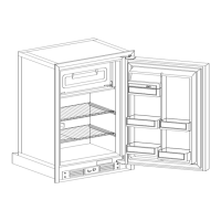
INSTALLATION
Length of
Field Supplied Wire
Less than 6 FT.
6 FT. to 12 FT.
12
FT. to 20 FT.
Unit Location
-
Be sure the refrigerator is not installed in
direct sunlight, or near a gas stove, heater or other heat gen
-
erating sources. A flanged mounting frame is provided around
the front of the refrigerator cabinet to allow build
-
in installa
-
tion.
You refrigerator should be located and secured on a solid sur
-
face within the vehicle.
Before installing the cabinet into the opening, check to see if
the A.C. power supply cord of the unit is properly connected
to the A.C. wall outlet and
if
the D.C. supply should be con
-
nected. In many cases, the D.C. supply can be connected from
outside the vehicle by means
of
the vent or access door.
Measure the opening and determine if you have the proper
clearances for installation. There is no need for allowing an
area around the cabinet for additional insulation as the
Norcold
refrigerator is well insulated and requires no additional insula
-
tion.
Place the refrigerator into the wall opening and secure it in place by
fastening the mounting flange
to
the wall through the holes provid
-
ed
~~
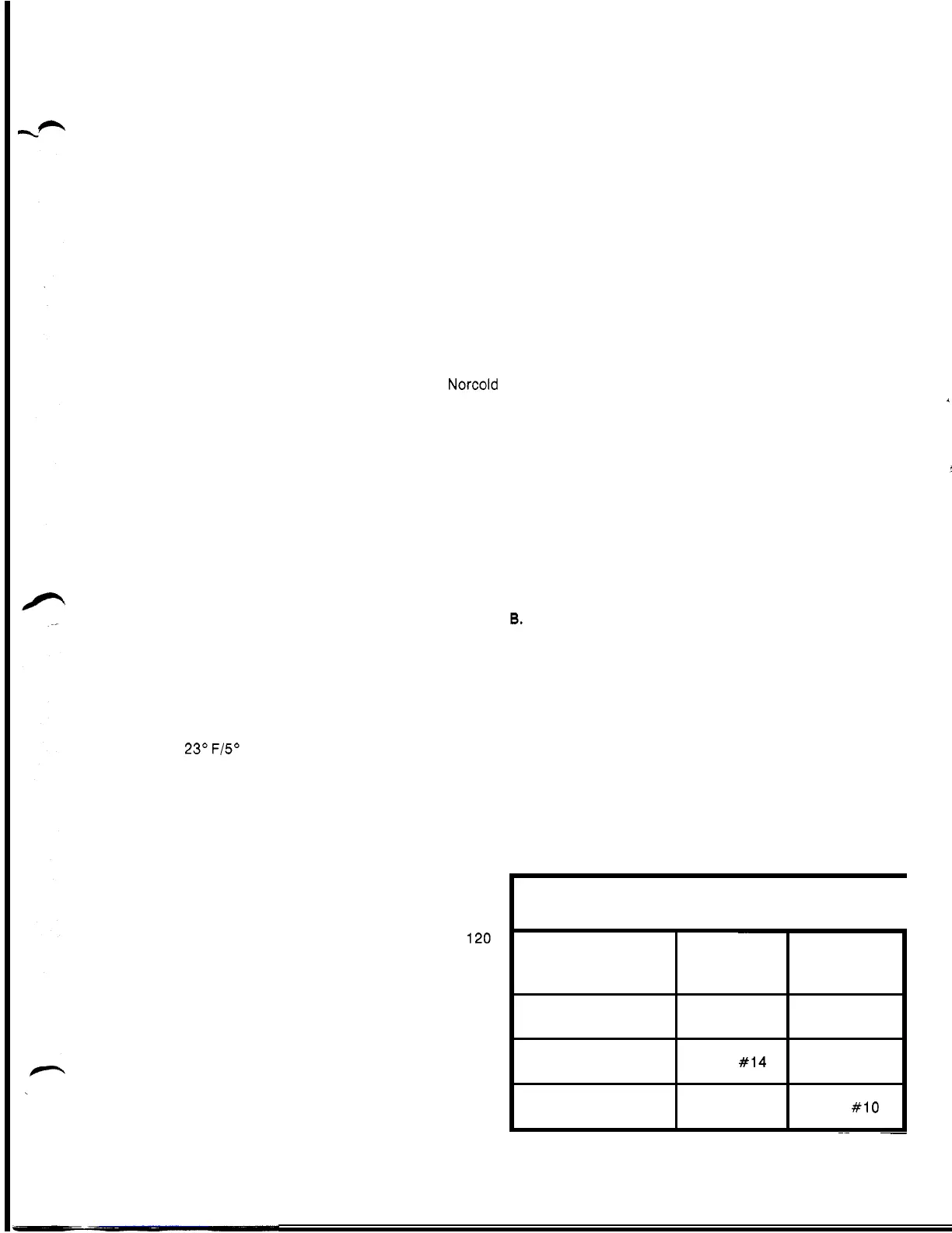
WIRE SIZE WIRE SIZE
DE
-
704 DE
-
828
AWG #14 AWG #14
AWG
#I4
AWG #12
AWG #12 AWG
#10
Venting
-
Unlike the absorber refrigerator, venting is not as
critical for efficient operation because the heat produced by
the condenser at the rear of the refrigerator is minimal.
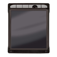
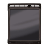
Please note the perforated access panel or kick plate at the
front base of the refrigerator. This panel allows air movement
to flow under the cabinet and over the inverter for cooling.
A small louver
-
type vent of approximately
4
"
x 16
"
area may
be installed at the top and at the bottom
of
the exterior wall of
the vehicle for outside venting purposes.
A combination of a roof jack and lower vent or two side vents
offers adequate venting for high outside ambient tempera
-
tures. If operation at low outside ambient temperatures is nec
-
essary (Below
23"
F/5" C) all exterior venting must be covered
to prevent possible compressor damage.
NOTE:
The more air circulating over the condenser (Located at rear),
the more efficient the refrigerator will operate. Failure to pro
-
vide the necessary ventilation will result in poor refrigeration.
Power
Supply
-
Provisions are made for connection of either
12 volts D.C. or 120 volts A.C. to the refrigerator. If both 12
VDC and 120 VAC are simultaneously supplied, a special relay
in the refrigerator control panel allows the unit to run on
120
VAC. To convert to D.C. power, the AC supply is simply
disconnected.
A. DC Power Connection
-
the D.C. supply connection is
located behind the perforated access panel at the bottom
front of the unit. Remove the screw from the top center of
the access panel and remove the panel. The D.C. terminal
box is located in the control (Inverter) assembly. The posi
-
tive and negative D.C. supply connections are located in
this terminal box.
The size of the wire from your 12 volt D.C. battery is depend
-
ent upon the distance between the refrigerator and the battery.
Refer to table 1 for wire size.
This recommended wire size is to prevent a voltage drop at
the refrigerator which is critical to D.C performance.
Use of wire sizes smaller than those listed may cause exces
-
sive D.C. running time and shorter battery life.
It is important that the 12 volt, D.C. supply be connected
di
-
rectly to the positive and negative posts of the battery and
that the wires are twisted or intertwined.
To the leads located in the terminal box, connect the positive
battery lead to the red wire and the negative battery lead to
the black wire. These splices should be soldered or connected
by means of an approved splice connector. Tape the splice
connections generously before replacing the terminal cover
box. The twisting of the lead wire nullifies the induction creat
-
ed by high voltage surges which contribute to radio and T.V.
interference.
A 15 amp fuse should be installed as close to the battery as
possible in the positive wire leading to the refrigerator. This
fuse will protect the wiring from the battery to the refrigerator
in the event of a short circuit.
CAUTION:
DO
NOT OPERATE REFRIGERATOR ON BATTERY ALONE.
THE BATTERY MUST HAVE A CHARGING MEANS SUCH AS
THE VEHICLE'S ALTERNATOR; IF NOT, THE BATTERY WILL
DISCHARGE IN A SHORT PERIOD OF TIME.
Further information on D.C. supplies can be found later in this
manual.
6.
AC Power Connection
-
The 120 volt A.C. power connec
-
tion is made by connecting the refrigerator's
A.C.
cord to a
standard
120
volt ground receptacle. See Fig. 1.
The
120
volt A.C. supply outlet, to which the refrigerator is
connected should be routed through the fuse panel or circuit
breaker that protects the vehicle when an outside power
source is used. This connection should be permanently wired
in accordance with existing governing codes. The use of an
extension cord is not recommended.
CAUTION:
4
i
IF AC POWER
IS
SUPPLIED BY AN ON
-
BOARD GENERATOR,
IT IS VERY IMPORTANT TO HOLD BOTH VOLTAGE AND FRE
-
QUENCY WITHIN THE TOLERANCES STATED IN THE FRONT
OF THIS MANUAL.
I
WIRE
SIZE
tables
for
field supplied
D.C.
cord
(to
battery)
~~
~
TABLE
1.
3