2
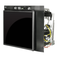
CONTROL PANEL CONFIGURATION
207 – Selector Switch (battery, electric, or propane.)
293 – Electric (AC) Thermostat.
217 – Flame Meter.
216 – Piezo Lighter.
294 – Propane Gas Control.
310 – Electric (AC) Power Indicator (green light - plug icon.)
311 – 12-Volt (DC) Power Indicator (green light – battery icon.)
OVERVIEW OF THE REFRIGERATOR CONTROLS
The Selector Switch (207) is used to select the power source: Propane Gas (flame symbol), AC
(electric plug symbol), 12-Volt DC (battery symbol), or “OFF” (power off symbol.)
The Electric AC Thermostat (293) controls the temperature setting when using electricity. The
Electric AC Power Indicator (310) will display a green-lighted plug symbol when AC power has
been selected.
The 12-Volt DC Power Indicator (311) will display a green-lighted battery symbol when DC power
has been selected.
When the Selector Switch (207) is set for propane gas, a (non-electric) Piezo Lighter (216) is used
to create a spark, which ignites the flame in the refrigerator burner. The Flame Meter (217)
shows if a flame is present in the burner. The Propane Gas Control (294) sets the temperature
setting of the refrigerator when operating in the propane gas mode.
 Loading...