Do you have a question about the Norcold N8DCX and is the answer not in the manual?
Provides maintenance, diagnostic, and repair information for N8DCX and N10DCX compressor refrigerators.
Details NORCOLD® compressor refrigerators certification under UL 60335-1 standards and UL compliance of electrical components.
Specifies installation must conform to N8DCX and N10DCX Series Installation Manual and comply with codes.
Emphasizes using only authorized NORCOLD® replacement parts to maintain safety, reliability, and warranty.
Provides contact information for technical support for resolving issues not covered in the manual.
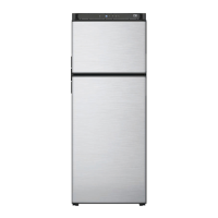
Locates and explains the refrigerator information label, including Model Number and Serial ID.
Details electronic control features, rough opening dimensions, and internal capacity for N8DCX and N10DCX models.
Covers DC voltage input requirements, fuse requirements, and resistance/amperage ratings for cooling fans and interior light.
Specifies the maximum allowable tilt angles for refrigerator operation (side-to-side and front-to-back).
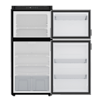
Identifies and describes components visible from the front of the refrigerator using an exploded diagram.
Identifies and describes components located on the rear of the refrigerator using an exploded diagram.
Ensures proper installation by checking ventilation, electrical safety, floor support, and securing the unit.
Explains the importance of proper airflow for cooling efficiency and longevity, warning against blocked vents.
Details DC power connection requirements to prevent interference, including independent circuits and proper wiring.
Instructs on correct DC polarity connection, warning that incorrect wiring will prevent operation.
Basic checks to perform before detailed diagnostics, including unit status, vents, and ambient temperature.
Lists and describes the components used for LED diagnostics, referencing figures 4.1 to 4.6.
Lists the necessary components for conducting self-diagnostics using an LED and connectors.
Provides step-by-step instructions and figures for connecting the LED and adapters to the control module.
Correlates LED flash counts with specific error descriptions and recommended diagnostic tests.
Lists common refrigerator problems with possible causes and corresponding diagnostic tests to perform.
Details fault codes (E1-E4), their meanings, and the specific troubleshooting steps or pages to refer to.
Tests DC supply voltage at the connector and terminals to ensure it stays within the operational range.
Checks if the exterior cooling fan is operating and measures DC voltage at the control module terminal.
Tests the motor start function by turning the unit off for five minutes, then back on to check for error codes.
Verifies input voltage, checks for unit overload, and assesses fan operation and coil cleanliness.
Tests the thermal protection of the control module, ensuring vents are clear, coils clean, fan operates, and temp is within limits.
Checks for disconnected wires, ON indicator light, DC power connection, and correct input voltage.
Checks thermistor connections, control board, magnet valve, and potential shorted wires.
Checks temperature settings, door seal, hinges, and latch for correct operation and excessive frost build-up.
Inspects condenser coil for restriction, checks voltage, and verifies fan operation.
Checks for blown DC fuse, wire gauge, and DC voltage at the control module, suggesting battery recharge if low.
Verifies input voltage, checks for unit overload, and disconnects thermistor wire to test if the unit still cuts out.
Addresses the E1 fault code, indicating the fresh food thermistor is not cycling properly and checks its connection.
Addresses the E2 fault code, indicating the freezer thermistor is not cycling properly and checks its connection.
Details fault codes E3 (voltage out of setting) and E4 (door open too long) and their respective causes.
Identifies components A through K shown in the wiring diagram, linking them to their descriptions.
Provides steps to safely disconnect power and remove the refrigerator from its enclosure.
Provides steps to reinstall the refrigerator into its enclosure and reconnect power supplies.
| Brand | Norcold |
|---|---|
| Model | N8DCX |
| Category | Refrigerator |
| Language | English |